Rayburn Heatranger 480GB Servicing Instructions Download Page 29

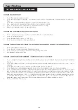
BURNER WILL NOT START

1.

Check that external wiring is correct.

2.

Check for 230V supply on terminal 1 at control box base, this will also determine if the thermostats are calling for 
heat.
Check that incoming Neutral conductor is correctly wired onto terminal 2.

3.

Press reset button to ensure that the control box has not gone to lockout.

4.

Check air pressure switch is in provide air condition and fan is running.

5.

If burner still refuses to start, change control box.

BURNER FAN RUNS WITH CONTINUOUS PRE-PURGE

1.

Check wiring to air pressure switch across terminal 8 & 11 at control box base.

2.

Check air pressure switch.

3.

Check fan inlet ducts and fan for blockages.

4.

Check plastic air tubes are correctly connected.

BURNER STARTS, FLAME NOT ESTABLISHED, CONTROL BOX GOES TO LOCKOUT, AFTER END OF SAFETY

1.

Check gas supply to valves is on.

2.

Check ignition is present after end of pre-purge period.

3.

Check start gas valve is energised and is opening during safety time.

4.

If necessary change control box.

BURNER STARTS FLAME ESTABLISHED, CONTROL BOX GOES TO LOCKOUT

1.

Check polarity of wiring for Live and Neutral to control box base. live to terminal 1. Neutral onto terminal 2 at control
box base.

2.

Check flame detection probe is correctly positioned. Ensure that the probe insulation is sound, free from cracks or
moisture.
Check that the probe is not in contact with other metallic parts of the burner.

3.

Check the burner is effectively earthed and boned to the incoming earth wire from the mains supply.

4.

Check for interference to the flame signal from the ignition spark. This can be determined with a d.c. micro-ammeter
(µA). Connect the meter between terminal 12 and the incoming wiring to the flame probe. Correct polarity of the 
meter connections must be correctly observed, with the positive side of the meter connected onto terminal 12 at 
the control box wiring base. If flame is established and the meter tends to move in a reverse direction this can be 
an indication that the ignition is causing interference to the flame signal. It may also be an indication that there is 
insufficient earth contact with the flame. A correct reading should be approximately 15 - 20 µA.

5.

Change control box if necessary.

28

TROUBLESHOOTING-BURNER

Fault Finding

Summary of Contents for Heatranger 480GB

Page 1: ...WARNING This information is a copy of an original archive therefore Aga cannot be held responsible for its continued accuracy...

Page 2: ...g Instructions Heatranger 480GB At the Heart of your Home DESN 511653 P A T A P P 2 2 8 0 7 4 7 A N D O T H E R G B I E P A T E N T S P E N D I N G 10 99 EINS 511382 PLEASE READ THESE INSTRUCTIONS BEF...

Page 3: ...to ensure that the necessary personal protective clothing is worn when handling where applicable the pertinent parts that contain any of the listed materials that could be interpreted as being injurio...

Page 4: ...service visit In your own interest and that of safety to comply with the law all gas appliances must be installed maintained by a competent person in accordance with the current gas safety installatio...

Page 5: ...PPLIES TO THE APPLIANCE HAVE BEEN ISOLATED SEE FIG 1 1 Open up burner access door Remove door and put in a safe place 2 Remove the 4 inner panel securing screws and remove panel 3 Remove the 3 plinth...

Page 6: ...urn off gas cock 2 Break gas cock union connection 3 Disconnect the 5 pin plug underneath the burner SEE FIG 3 4 Undo the burner central locking nut 5 Remove 2 fan mounting plate nuts SEE FIG 4 6 With...

Page 7: ...in between hotplate ribs on underside 2 Examine soft rope seal located around hotplate aperture in top plate Replace if frayed or damaged 3 Replace hotplate ensuring the underside ribs lie over the ov...

Page 8: ...burners mixed up 1 Clean heads with soft brush and inspect for damage or wear 1 Clean between the blades of the fan impeller with a small brush and tip upside down to remove any residue 2 Spin the mo...

Page 9: ...et button COOKER BURNER Follow procedure as above for boiler burner BOILER BURNER Reset the control box open the gas inlet cock allowing the burner to restart When the burner is in run condition close...

Page 10: ...ecified CO 93 ppm MAX CO2 8 5 9 0 Cooker Burner Switch off the boiler burner and repeat the above procedure with the cooker burner To sample the flue gases from the cooker burner lift up the R H insul...

Page 11: ...Steps 1 to 3 and BURNER REMOVAL Steps 1 to 6 1 Remove 8 burner head securing screws 2 Disconnect plug on fan mounting plate SEE FIG 12 Follow instructions in sections BURNER ACCESS Steps 1 to 3 BURNER...

Page 12: ...See Fig 14 NOTE DO NOT OVER TIGHTEN ELECTRODE CLAMP SEE FIG 13 Follow instructions in sections BURNER ACCESS Steps 1 to 3 BURNER REMOVAL Steps 1 to 6 and DISMANTLE BURNERS Steps 1 to 2 1 Remove securi...

Page 13: ...ove ignitor 8 Fit new ignitor re assemble in reverse order SEE FIG 16 Follow instructions in sections BURNER ACCESS Steps 1 to 3 and BURNER REMOVAL Steps 1 to 3 1 Remove control boxes 2 Break 2 gas pi...

Page 14: ...l fixing screws 4 Remove cover panel It will be necessary to disconnect the push on tags from the selector switch SEE FIG 19 5 Remove the four control panel fixing screws 6 Tilt the chassis forward fr...

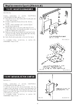
Page 15: ...Replacement of parts Electrical FIG 20 DESN 511140 14...

Page 16: ...t The thermostat should be mounted with tag P at the right hand side looking from back Take care to push thermostat phial correctly into the pocket provided 4 Re connect push on connector wires The wh...

Page 17: ...capillary which pass into the oven at the top left hand corner The thermostat phial is located in a slot at the top front of the oven 4 Slacken the single screw where the phial passes through the roa...

Page 18: ...e programmer inserting the top base with the bottom clip 6 Refix the mounting brackets to the control chassis To complete follow instructions in section RE ASSEMBLE Steps 3 to 6 SEE FIG 27 Follow inst...

Page 19: ...an assembly 5 Remove 2 venturi securing screws 6 Remove fan venturi assembly and gasket from fan 7 Fit new fan re assemble in reverse order SEE FIG 29 1 Remove 2 fan cover securing screws remove cover...

Page 20: ...he chassis backwards into position with the four screws 3 Thread the two wires for the selector switch through the aperture and connect them onto the rear of the selector switch fitted in the outer pa...

Page 21: ...65 C then the pump overrun thermostat operates and switches on the pump until the overrun thermostat switches back BOILER This thermostat is a safety cut out device which is intended to operate if th...

Page 22: ...CYLINDER STAT ZONE VALVE S ETC IF FITTED PUMP SUPPLY THE CIRCULATING PUMP MUST BE CONNECTED DIRECTLY TO THIS SUPPLY PUMP SUPPLY THE CIRCULATING PUMP MUST BE CONNECTED DIRECTLY TO THIS SUPPLY 3 AMP PE...

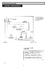
Page 23: ...Electrical Controls 22 CONTROL CIRCUIT BOILER FIG 30...

Page 24: ...Electrical Controls 23 CONTROL CIRCUIT COOKER FIG 31...

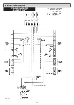
Page 25: ...Electrical Controls 24 WIRING DIAGRAM BURNER ONLY FIG 32...

Page 26: ...25 WIRING DIAGRAM APPLIANCE Electrical Controls FIG 33...

Page 27: ...individual controls refer to the section on Replacement Parts and for wiring continuity checks refer to Figs 32 33 34 and 35 for detailed and schematic wiring layouts 1 To check out the electrical wir...

Page 28: ...STAT ACTIVATED IS THERE 230V BETWEEN COOKER OVERHEAT STAT AND NEUTRAL REPLACE COOKER OVERHEAT STAT RESET OVERHEAT THERMOSTAT THERMOSTAT OR WIRING FAULT YES NO NO YES NO YES CHANGE CIRCULATING PUMP IS...

Page 29: ...ESTABLISHED CONTROL BOX GOES TO LOCKOUT 1 Check polarity of wiring for Live and Neutral to control box base live to terminal 1 Neutral onto terminal 2 at control box base 2 Check flame detection probe...

Page 30: ...29...

Page 31: ...30...

Page 32: ......

Page 33: ......

Reviews: