


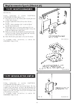


SEE FIG 13 & 15
Follow instructions in sections BURNER ACCESS, Steps
1 to 3, BURNER REMOVAL, Steps 1 to 6 and
DISMANTLE BURNERS, Steps 1 to 2.
1.
Remove securing nut and disconnect H.T. lead from
ignition electrode.
2.
Slacken nut and bolt on electrode clamp.
3.
Slide electrode forward and away from clamp.
4.
Fit new electrode in reverse order, set gap and
position (See Fig. 14).
NOTE: DO NOT OVER TIGHTEN ELECTRODE CLAMP.
SEE FIG. 13
Follow instructions in sections BURNER ACCESS, Steps
1 to 3, BURNER REMOVAL, Steps 1 to 6 and
DISMANTLE BURNERS Steps 1 to 2.
1.
Remove securing nut and disconnect H.T. lead from
flame sensing probe.
2.
Remove fixing screw.
3.
Slide sensing probe forward and away from clamp.
4.
Fit new sensing probe in reverse order, set gap and
position (See Fig. 14).
NOTE: DO NOT OVER TIGHTEN SENSING PROBE
CLAMP
Replacement of parts (Burner)
FLAME SENSING PROBE
IGNITOR ELECTRODE
FIG. 13
FIG. 15
DESN 511410
DESN 511133
11
Summary of Contents for Heatranger 480GB
Page 15: ...Replacement of parts Electrical FIG 20 DESN 511140 14...
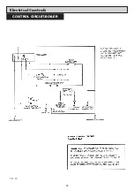
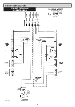
Page 23: ...Electrical Controls 22 CONTROL CIRCUIT BOILER FIG 30...
Page 24: ...Electrical Controls 23 CONTROL CIRCUIT COOKER FIG 31...
Page 25: ...Electrical Controls 24 WIRING DIAGRAM BURNER ONLY FIG 32...
Page 26: ...25 WIRING DIAGRAM APPLIANCE Electrical Controls FIG 33...
Page 30: ...29...
Page 31: ...30...
Page 32: ......
Page 33: ......


