18
Heat exchanger
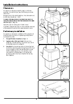
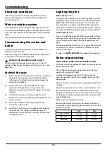
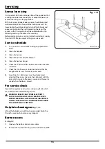
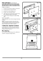
Fig. 1.22 &
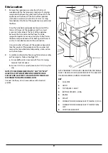
Fig. 1.23
BEFORE REMOVING SERVICE ACCESS COVERS ENSURE
THAT ALL ELECTRICAL ACCESS TO THE APPLIANCE HAS
BEEN SWITCHED OFF (SWITCH OFF AND REMOVE PLUG).
SEE
Fig. 1.22
&
Fig. 1.23
1.
Remove the controls door and place in a safe position.
2.
Remove both thermostat controls knobs.
3.
Remove the 2 cover panel fixing screws.
4.
Remove 4 screws securing control box.
5.
With bracket on rear of control box, hang the controls
box on the bottom edge of control aperture.
6.
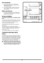
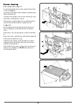
Remove 4 wingnuts securing access plate. (See
Fig.
1.24
).
Remove access plate
R
.
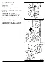
Using a suitable brush, clean the heat exchanger from above
and below.
NOTE
: The insulation used on the inside surface of the
combustion chamber is delicate. Great care must be taken
when cleaning the heat exchanger not to abrade it. No
attempt should be made to clean the insulation.
Combustion chamber insulation
Remove boiler burner assembly as previously described.
Check insulation for any signs of deterioration or physical
damage and replace if necessary.
Flue cleaning
Brush out cooker and boiler flueways with a suitable brush.
Check the assembly of the draught diverter.
DESN 512150
DESN 512144
DESN 512145
Fig. 1.22
Fig. 1.23
Fig. 1.24
REMOVE 4 SCREWS

