SECTION 8
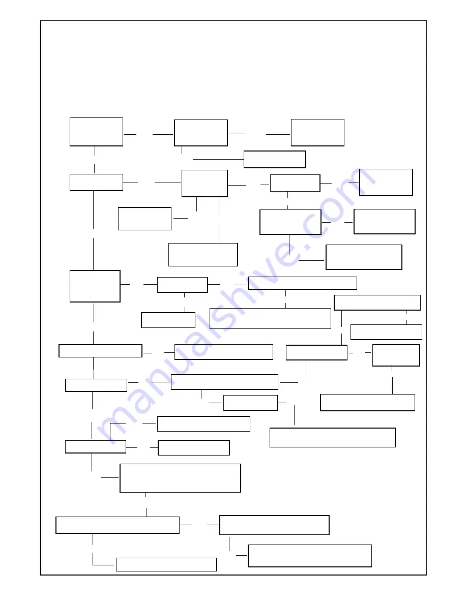
FAULT FINDING CENTRAL HEATING
Before trying to operate the boiler make sure that:
- All gas supply cocks are open and the gas supply has been purge of air.
- The heating system pressure is at least 1 bar min to 1.5 bar Max.
- Main Switch on and power indicator light is on
- Select “Winter” (Fig.37 item 1A)
- Central Heating control knob to maximum (Fig.37 item 4)
- Ensure external controls calling for heat (Room stat/Timeclock/TRV)
Does power
indicator light
illuminate?
No
Is 230 at L- N
connections on
control board
No
Check/Replace
external Fuse and
supply
Yes
Replace On/Off Switch
Does the pump run
Is low pressure
in the system
Re-pressure the
system
Is 230V at pump
Check/Replace
pump if necessary
No
Yes
Yes
No
Yes
Is there continuity at
summer/winter switch
Replace
summer/winter switch
Check /Replace Timeclock
if OK Replace control board
No
Yes
No
Is the fan running
at Maximum
speed
Yes
No
Is 230 V at Fan
No
Is the fl ow temperature less than 95°
Yes
Check/Replce Fan
Check\replace fan modulating board
Is there a gas supply for the applianced
Is the fl ue temperature less than 95°C
Yes
Check Gas supply
- Check / Replace heating sensor
- Check / Replace the overheat thermostat
No
Yes
No
-
END CENTRAL HEATING TEST
FAILED FLUE TEMPERATURE
- Check operating system
No
Check/Replace Air fl ow pressure switch if ok
Check/Repalce control board fuse
Is the fan Oscillating on-off
Yes
Yes
Does burner light?
No
Is there spark ignition
Check \Replace
Spark electrode
No
No
Check\Replace condensing
trap and\or condensing sensor
Yes
Is there 230 V on the Gas Valve
Yes
Check\Replace Gas Valve
Is the burner on - off
Yes
Check \Replace control board fuse
Yes
Check\Replace Gas Valve
Yes
Does the gas pressure remain at min for
few minutes and than increase to the set
level
Yes
Yes
Is the burner shut down by overheat stat
Yes
Yes
No
Check\Replace Low
water Pressure Switch
Yes
40
Summary of Contents for 780 Series
Page 2: ......
Page 7: ...7 Fig 3 OVERALL DIMENSION ...
Page 34: ...34 Fig 45 Fig 44 Fig 46 ...
Page 36: ...36 Fig 48 Fig 47 Fig 49 Fig 50 Fig 51 ...
Page 42: ...Fig 59 42 SECTION 9 ELECTRICAL SYSTEM DIAGRAM ...
Page 46: ...79 83 105 46 50 27 16 39 17 2 22 100 1 4 5 11 8 SECTION 11 ...
Page 49: ...49 ...
Page 50: ...COD 0017LIB06010 2 03 2010 ...


