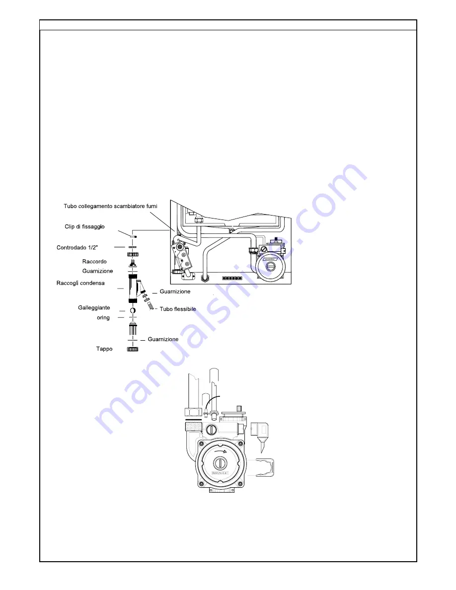
7.20 TO REMOVE/REPLACE CONDENSING
TRAP (fig.55).
7.20.1
Remove the casing (sect 7.3) and lower
the instrument panel .
7.20.2
Remove the securing clip and pull
out the plastic pipe that connect the
condensing trap at the heat exchanger.
7.20.3
Unscrew the nut that fasten the
condensing trap to the backframe and
remove it.
7.20.4
Replace in reverse order.
38
7.21 TO REMOVE/REPLACE PUMP (fig. 56).
7.21.1
Remove front casing (sect 8.1).
7.21.3
Detach the supply wire connector from the
pump.
7.21.4
Remove the securing clip at the pump
manifold, the pressure gauge and the
expansion vessel pipe.
7.21.5
Unscrew the nut to the CH pipe and remove
the pump.
7.21.6
Replace in reverse order.
Fig. 56
Fig. 55
Summary of Contents for 780 Series
Page 2: ......
Page 7: ...7 Fig 3 OVERALL DIMENSION ...
Page 34: ...34 Fig 45 Fig 44 Fig 46 ...
Page 36: ...36 Fig 48 Fig 47 Fig 49 Fig 50 Fig 51 ...
Page 42: ...Fig 59 42 SECTION 9 ELECTRICAL SYSTEM DIAGRAM ...
Page 46: ...79 83 105 46 50 27 16 39 17 2 22 100 1 4 5 11 8 SECTION 11 ...
Page 49: ...49 ...
Page 50: ...COD 0017LIB06010 2 03 2010 ...


