


20
User’s manual HANDHELD TOUCH RADIO
User’s manual HANDHELD TOUCH RADIO
Pag.22
Pag.23
Vers. 01 of:07.04.14
Vers. 01 of:07.04.14
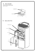
Loading the auger
MENU
USER
SCREW FEEDING
SCREW FEEDING
CHRONOTHERMOSTAT
AIR-PELLET SET
STOVE STATE
USER
MANUFACTURER
ENGINEER
MENU
USER
MANUFACTURER
ENGINEER
USER
USER
COMFORT CLIMA
COMFORT CLIMA
COMFORT CLIMA
COMFORT CLIMA
ENABLE COMFORT
ENABLE COMFORT
ENABLE COMFORT
RESTART DELTA
RESTART DELTA
SHUTDOWN DELAY
SHUTDOWN DELAY
SHUTDOWN DELAY
SHUTDOWN DELAY
ENABLE COMFORT
ENABLE COMFORT
COMFORT CLIMA DELTA
COMFORT CLIMA DELTA
RESTART DELTA
SHUTDOWN DELAY
SETTINGS
SCREW FEEDING
CHRONOTHERMOSTAT
AIR-PELLET SET
STOVE STATE
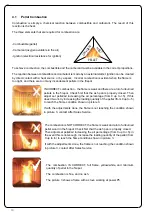
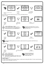
ALWAYS EMPTY THE BRAZIER BEFORE TURNING THE STOVE ON AND ALWAYS CHECK
THAT ALL NONE OF ITS HOLES IS CLOGGED NEVER EMPTY THE RBAZIER INSIDE THE HOPPER.
FIRE HAZARD.
Carry out this operation to facilitate stove’s first start operations; You should also check that you have introduced pellets
into the hopper and wait until the stove is in “SHUTDOWN” or “FINAL CLEANING” mode. The number expressed in sec-
onds indicates the rotation time of the infeed screw during the first loading cycle. Once this time has elapsed, the infeed
screw stops immediately and then pellets are emptied from the grate before turning on the equipment.
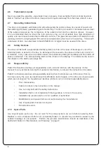
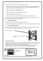
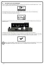
Below are given the steps for accessing the relative menu.
Press the key “access
menu” to access
the
MENU page
Press the key
“confirm”
to access the
USER page
At the end of the auger loading, the display shows 0 “and automatically switches to the USER menu page.
Press the key for several times until the Stand-by page is displayed.
Setting operating temperature and power:
Set the two values following the indications given in the chapter “Description of thr display”
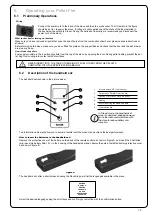
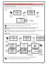
Turning the device on
Keep the key ON/OFF pressed for a few seconds to turn on the stove.
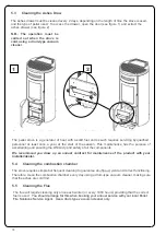
Press CONFIRM to enable
the rotation of the auger
The appearance of the message “ADJUST THE RDS SYSTEM” indicates that the initial parameter testing procedure
and calibration has been unsuccessfully. This indication does not cause stove blockage (see the SIGNALLING POP UP
section).
On the display of the handheld set appears the following:
Press and hold the ON/OFF button to turn off the stove door, and reset any alarms triggered.
In case the infeed screw operations described avobe have not been executed, the stove may fail to turn on. In this case,
carry out the operations described above and empty the brazier and reset the alarm.
If the stove still fails to turn on, check that the grate is properly installed and perfectly adherent to the base, and also check that
there are no deposits that prevent the smooth passage of air to enable ignition. If the problem persists, contact the support ser-
vice.
Sequence of ignition phases
SWITCH-ON- initial pellet loading phase;
WAIT FLAME - flame
development wait
phase;
FLAME PRESENT - flame stabilization
phase and reduction of combustible
inside the brazier;
What happens if the batteries are empty?
If the battery is discharged, within the
“drop” is shown a symbol that indicates
that the battery is empty, while maintain-
ing active the features of your device.
WORK - operation phase
described in
the dedicated chapter;
As soon as the level of the battery
prevents the radio communication the
handheld set displays on full screen the
picture of empty battery and all device
functions are locked until the batteries
are replaced
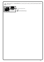
CONNECT AN EXTERNAL THERMOSTAT WITH A SIMPLE DRY CONTACT, THEREFORE, NOT POWERED. MORE-
OVER, WE RECOMMEND YOU USE A THERMOSTAT WITH A MINIMUM OFFSET OF 3°C IF YOU INTEND TO USE
THE COMFORT CLIMA FUNCTION.
Operating phases of the appliance
Modulation
During the work phase, the appliance should reach the room temperature set; when this condition is met, the stove switches to
MODULATION mode in which fuel consumption and ventilation are minimum.
If you wish to detect the ambient temperature by means of an external thermostat (optional), this must be connected to
the appropriate connector on the rear side of the stove; and you will have to activate the reading in “SETTINGS - EN -
ABLE THERMOSTAT.” On display appears the writing TON / TOFF based on thermostat request.
Comfort climate
The activation of this function enables the stove to reduce pellet consumption by activating the modulation phases, after the desired
temperature has been reached. Subsequently, the stove checks that the temperature is maintained steady for a preset time. If this
condition is met, it automatically switches off, and on display appears the writing ECO.
The stove turns on again when the temperature drops below the set threshold.
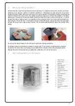
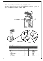
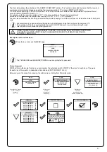
Below are given the steps for accessing the relative menu.
Press the key
“access menu” to
access
the
MENU page
Press the key
“confirm”
to access the
USER page
Once you have accessed the Climate Comfort menu, it is possible to operate on the 3 types of settings dedicated to the function:
Press the key for several times until the Stand-by page is displayed.
Press the key “selection” for
“selection”
to switch to the second page
of USER MENU and select
CLIMATE COMFORT.
6.9 Operating Phases of the Stove


