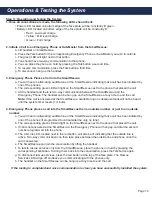
Step 11: Operating and Testing the System
1. Once all connections are made, the following LEDs should be lit:
• Power LED, located on bottom edge of the face plate, will be constantly lit green.
• Battery LED, located on bottom edge of the face plate, will be constantly lit:
• Red = Low level charge
• Yellow = Mid level charge
• Green = Full charge
2. Initiate a Call to an Emergency Phone or Sub-Master from the SmartRescue:
a. Lift handset on SmartRescue.
b. Press the Talk button for the corresponding Emergency Phone or Sub-Master you wish to call into.
c. The green LED will light next to that button.
d. You should have two-way communication to that phone.
e. You can place the phone on hold by pressing the Talk button a second time.
f. To resume communication, press the Talk button a third time.
g. To disconnect, hang up the handset.
3. Emergency Phone Places a Call into the SmartRescue:
a. You will hear an alternating audible tone at the SmartRescue indicating that a call has been initiated by
one of the phones.
b. The corresponding green LED will light on the SmartRescue next to the phone that placed the call.
c. Lift the handset and there is two-way communication between the SmartRescue and the
Emergency Phone. The handset can be hung up on the SmartRescue at any time to end the call.
Note:
If the call is answered at the SmartRescue, available ring on subsequent calls will not be heard
until the system timer resets (1 minute).
4. Emergency Phone places a call into the SmartRescue then an outside number, or just to an outside
number:
a. You will hear an alternating audible tone at the SmartRescue indicating that a call has been initiated by
one of the phones (if programmed to call outside line only, no tone).
b. The corresponding green LED will light on the SmartRescue next to the phone that placed the call.
c. If call is not answered at the SmartRescue, the Emergency Phone will hang up and dial the second
number programmed into the phone.
d. The CO Line LED, located next to the red button, will also be lit indicating that the outside line is
active. Two-way communication can then take place between the outside line and phone once the
call is answered.
e. The SmartRescue can join the conversation by lifting the handset.
f. To talk to rescue services only from the SmartRescue, place the phone on hold by pressing the
corresponding Talk button. To bring them back into the conversation, press the Talk button again.
g. To disconnect rescue services, press the red button at the top of the face plate. The Rescue
Services LED will go off and leave you communicating with the phones only.
h. The handset on the SmartRescue can be hung up at any time to end the call.
If the testing is completed and voice communication is clear, you have successfully installed the system.
Appendix
Page 11
Installation:
• Mount the Sub-Master to the wall in desired location
• Run twisted, 22 or 24 AWG, 4 wire cabling to connect the Sub-Master to the SmartRescue
•
Emergency Phones MUST be in Consolidator Mode (see page 12)
Operation:
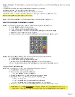
• Lift handset
• To speak to individual phones connected to SmartRescue:
Press *1 (Phone 1)
Press *2 (Phone 2)
Press *3 (Phone 3)
Press *4 (Phone 4)
Press *5 (Phone 5)
If you wish to speak to all phones, press *0
Press #1 (Phone 6)
Press #2 (Phone 7)
Press #3 (Phone 8)
Press #4 (Phone 9)
Press #5 (Phone 10)
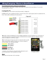
Wiring Diagram:
R
U
R
U
1
4
7
*
3
6
9
#
1
4
7
*
3
6
9
#
Ports for Optional
2300-630SM Phone
2300-630SM Sub-Master Installation & Operation
The 2300-630SM is an optional Sub-Master Phone that may be remote mounted and used to call any of the phones
connected to the SmartRescue. Up to (2) 2300-630SM phones may be connected to one SmartRescue.
Summary of Contents for SmartRescue 10
Page 7: ...Page 7 Plug In Transformer...


