background image

High Power Repeater (RC5040-20T) Installation & Operation

Page 15

Installation Notes

• These products are designed to be maintained by professional security technicians

• Products are tested for indoor use

• All products should be manually tested weekly

Items Included

• One 120vac @ 20VA/12vac @ 1000mA power transformer

• Three drywall anchors

• Three mounting screws

Select the Frequency Band

EchoStream devices are able to use a range of radio frequencies, and must be configured for your geographic area. 

This device ships with a default frequency range of 902-928 MHz for use in North America.

1. Use a small screwdriver to press the top housing release tab and separate the housing  

2. Place a selection jumper on the frequency band selection pins appropriate to your geographic area

Choose Messaging Mode

The EchoStream commercial mesh network includes two kind of messaging: broadcast messaging and directed 

messaging. The Repeater includes a messaging selection option to protect the integrity of the system. The Repeater 

ships with a default setting of broadcast messaging. If you are installing the Repeater in a directed messaging 

network, you will need to configure it.

Note:

 For UL 2560 installations, directed messaging must be selected.

Note:

 If directed messaging is selected, you will need to configure the network ID (NID).

3. To set the Repeater to directed messaging, remove the selection jumper installed on the messaging mode 

    selection pins.

Connect Power Cabling

Power must be connected to the Repeater. To connect power:

4. Use a small screwdriver to press the housing release tab on the top or bottom of the Repeater; separate the housing.

5. Connect power cabling

    • Wire should be two conductor 20AWG (or larger) stranded-tinned copper with PVC insulation rated to 300 volts at 

      80°F (26°C). Wire length should not exceed 328 feet (100 meters).

Note:

 For all UL installations, cabling must be UL Listed or Recognized, Class 2 wire suitable for the application. Use 

two conductor 20 AWG (or larger) stranded-tinned copper, rated 300 volts, 60°C minimum. Wire length should not


exceed 328 feet.

   • Route the cable from the transformer to the unit through the left side of the Repeater, or through the oval knock-out 

     section in the rear.

   • Torque screw terminal to 0.25 N-m (2.18 inch-pounds).

Note:

 Do not secure transformer for Canadian installations.

Connect Battery Power

The repeater is shipped with a fully-charged backup battery. You will need to connect the battery:

6. Plug the connector cable from the backup battery into the battery connector.

Register the Repeater

Although the Repeater is functional upon startup, RATH® strongly recommends that you register it. RATH® 

recommends all Repeaters be supervised. When supervised, the RC5040-20T Repeater will send a check-in


message every 20 minutes.

Note:

 In UL 2560 installations, the Repeater sends a check-in message every 20 minutes.

Note: 

Registration and supervision are required for UL installations.

Caution: 

The reset bit will not be sent when the Repeater has a low battery. Before registering the repeater, ensure 

the battery is fully charged.

Summary of Contents for SmartAlert

Page 1: ...artAlert Software Wireless System N56W24720 N Corporate Circle Sussex WI 53089 800 451 1460 www rathcommunications com RP8500SA Ver 1 12 18 Made in the USA 3 Year Warranty Installation Operations Manu...

Page 2: ...ly assist with site preparation installation and maintenance It is our sincere hope that your experience with us has and will continue to surpass your expectations Thank you for your business The RATH...

Page 3: ...perform any of the following functions Emergency call and device alert display monitor Interaction to see emergency call details view system alerts or master information Access point to configure Smar...

Page 4: ...twork cable from the network interface port on the PC into the router or network being used The keyboard and mouse can both be plugged into available USB ports on the PC Power on the system Using a No...

Page 5: ...nagement Studio and sign into the database Open the properties page for the database and click on the security option Make sure SQL Server and Windows Authentication mode is selected Open the SQL Serv...

Page 6: ...older Move the shortcut to the desktop SmartAlert Software on Non Server PC Create a new folder in the root of C called NurseCall C NurseCall Locate RATHNURSECALLSE Shared folder from the server Open...

Page 7: ...ority level is set in programming as some devices require a higher importance than others Duration This indicates how long the call has been active A tone will sound when a call comes in if the volume...

Page 8: ...button To see a list of all scheduled reports use the List tab To delete a scheduled report select the desired report from the list then click the Delete button Resident Patient Database The Resident...

Page 9: ...have to enter in your SMTP Outgoing Mail Server User Name Password and sending email address in these fields to send email notifications Nurse Caregiver Database The Nurse Caregiver Database is the ic...

Page 10: ...r the phone number in an email format as shown below and select the desired criteria AT T phone txt att net T Mobile phone tmomail net Sprint phone messaging sprintpcs com Verizon phone vtext com US C...

Page 11: ...button Shift Database The Shift Database is the icon used to define shift times and assign nurses caregivers to shifts To define the start and end time for a shift select the desired shift tab and ent...

Page 12: ...arameters are selected click the Print button to generate the report Two report types Detail and Summary can be selected Detail Reports display the call details of every call that has been placed with...

Page 13: ...nursecall com The Area Control Gateway RC6080 bridges the proprietary commercial mesh network to a standard TCP IP over Ethernet LAN adding unique capabilities to IP enabled software applications Page...

Page 14: ...ration To test place the system in test mode activate an end device and ensure an appropriate response RF Signal Propagation While wood drywall and glass usually let the RF signals pass some materials...

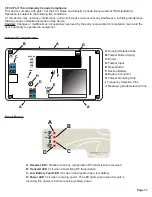
Page 15: ...Power must be connected to the Repeater To connect power 4 Use a small screwdriver to press the housing release tab on the top or bottom of the Repeater separate the housing 5 Connect power cabling Wi...

Page 16: ...ac 60 Hz 250 mA Power Supply 120vac 20VA 12vac 1000mA Battery Capacity 3 6vdc nominal 2900 mAh Typical Backup Battery Life 24 hours Operating Frequency 902 928 MHz USA Battery Charger Operating Enviro...

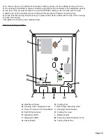
Page 17: ...e user s authority to operate the equipment A Housing Release Tabs B Tamper Button Spring C Power D Tamper Input E Reset Button F Backup Battery G Battery Connector H Tamper Mounting Hole I Frequency...

Page 18: ...strength efficiency Area Control Gateway RC6080 Installation Operation Transmitter Repeater Receiver Installation Notes These products are designed to be maintained by professional security technician...

Page 19: ...ng tamper spring is in place and makes contact with the top of the housing 9 Close the housing 10 Tighten the housing cover release screw A Wall Mount Holes B Housing Cover Release Screw C Power Conne...

Page 20: ...ndicates that the RC6080 is using a static IP address other than the default Green indicates that the RC6080 is using a dynamic IP address obtained from the network No illumination indicates that the...

Page 21: ...y all copies of the SmartAlert Software 4 COPYRIGHT All title and copyrights of the SmartAlert Software and any copies thereof are owned by RATH All title and intellectual property rights of content w...

Reviews: