


Page 3
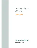
36”
10”
8”
9”
3”
1-9/16”
4-1/4” 4-1/4”
9-1/4”
5-1/4”
3”
3”
11”
12”
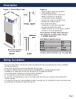
Description
Safety Guidelines
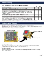
Figure 1: Front & Back View
FRONT
BACK
Bottom of Call Station
to Center Button
• ADA compliant (hands free operation)
• LED call status indicator
• Powder coated aluminum construction
• NEMA 4 enclosure for electronics
• Conduit holes for easy installation
• Security torx screws for internal access
• Weather and vandal resistant
• Blue beacon and strobe
• Strobe turns on upon phone activation
• Recessed illuminated face plate
• Ability to program up to 5 emergency numbers*
• Remote or on-site programmable**
• Save these instructions. This manual contains important instructions that will assist you during installation
and with maintenance.
• Keep all the components secure and protected during storage.
• Be careful of finished surfaces during transport and installation to avoid damaging the finish.
• Installation and maintenance should only be performed by qualified electricians.
• It is recommended a minimum of 2 people perform installation.
• Do not install phone during extreme weather conditions.
• Do not touch uninsulated phone wires or terminals unless the phone line has been disconnected at the
network interface.
• To comply with Americans with Disabilities Act (ADA) requirements, the Call Station must be mounted so that
the push button is less than 48” above the ground.
Features:
Height
36”
Width
10”
Depth
8”
Thickness of Aluminum*
0.090”
Weight
29 lbs.
Call Station Specifications:
*Stainless Steel Call Stations are 14 Gauge Steel
*Not applicable for 2-Way Radio application
**Not applicable for 2-Way Radio, Cellular,
or 900 MHz application