background image

Page 7

Phone Testing

Did you hear a dial tone?
Did the strobe start flashing immediately after the button was pushed?
Did the red LED become a solid light when you pushed the button?
Did the red LED flash and approximately 15-20 seconds later the called party started 

talking to you? (Delay is due to the phone telling the other party your location via the 

“Location Message”)
Can you hear the other party clearly? (If not, see “Adjust Speaker” below)
Can the other party hear you clearly? (If not, see “Adjust Microphone” below)
When the party you called hangs up, does the strobe stop?

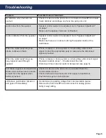
If you have answered YES to all questions, you have successfully installed and tested 

the phone. If you answer NO to any question, proceed to the Troubleshooting Section.

Push the emergency button on the front of the Call Station:

Yes

No

*RATH® recommends the Call Station be tested on a regular basis to ensure proper operation.

Adjusting the Volume
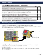
Volume Adjust VR1

Mic Sensitivity VR2

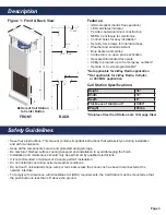
If the volume is too low or high, adjust it by referring to the diagram and instructions below. 

Note:

 Refer to the instructions under “Programming the Phone” to access the circuit board. Reinstall the cover on 

the NEMA 4 enclosure and close the Call Station when finished.

Adjusting the Microphone:

If the person you are calling reports your voice is not loud enough, increase the Microphone Sensitivity by 

adjusting VR2 a 1/4 turn clockwise (requires a small Phillips screwdriver).

Adjusting the Speaker:

If the voice of the person you call is not loud enough in the phone speaker, increase the volume by adjusting 

VR1 a 1/4 turn clockwise. 

RATH® SmartPhone

Summary of Contents for 2100-CP9

Page 1: ...Call Station Installation Operations Manual 36 Emergency Call Station 2100 CPL Landline 120v Call Station 2100 CPC Cellular 120v Call Station 2100 CP9 900 MHz 120v Call Station 2100 CPT 2 Way Radio 1...

Page 2: ...to remotely assist with site preparation installation and maintenance It is our sincere hope that your experience with us has and will continue to surpass your expectations Thank you for your business...

Page 3: ...tenance Keep all the components secure and protected during storage Be careful of finished surfaces during transport and installation to avoid damaging the finish Installation and maintenance should o...

Page 4: ...rogrammed remotely secure the front assembly to the back panel and reinstall the 12 screws to the sides of the unit If the phone will be programmed on site proceed to the directions for On Site Progra...

Page 5: ...and narrow or wide bandwidth The antenna is installed and tuned at the factory Call Stations using 2 Way Radio are not ADA compliant the button must be pushed and held to talk and let go to listen No...

Page 6: ...st interval is 1 minute A Press 8 Enter 3 digit number in minutes Ex 2 minutes 002 Step 5 To Exit Program Mode A Press Stop for 3 seconds Step 1 To Begin Program Mode A Call into phone by dialing the...

Page 7: ...roceed to the Troubleshooting Section Push the emergency button on the front of the Call Station Yes No RATH recommends the Call Station be tested on a regular basis to ensure proper operation Adjusti...

Page 8: ...m is not providing a disconnect signal Contact the appropriate party to make sure the disconnect signal is provided When the called party hangs up busy signal is heard through speaker Phone company or...

Page 9: ...rd Play Pause Stop Constant Strobe to 900 MHz Radio or Cellular y r e t t a B Communication Source LED for Panel FRONT COVER Note If using landline phone cable will just run out of the bottom of the N...

Reviews: