background image

- 11 - 


2.3 Installation 


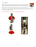
Step 4

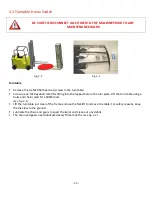
 - If installing a ramp, place the ramp by locating the ramp shoulder bolt and placing it 

into the slot in the ramp. It is highly recommended to anchor the ramp to the floor. 

(See Fig. 2-6)


Step 5

 - Affix the carriage onto the corresponding position on the mast and fasten with four 

M8 bolts. 

(See Fig. 2-7)

 Insert the connector plugs on the front of the carriage into the receptacles. 

(See Fig. 2-8)


Do not force the connectors together. 
 

Note: The Eagle 2000A will only have one receptacle for the load-height sensor.


Fig. 2-7 


Fig. 2-8* 


Fig. 2-6 

Summary of Contents for Eagle 2000A Series

Page 1: ...rations Manual Eagle 2000A Series Stretch Wrapper READ ALL INSTRUCTIONS CONTAINED IN THIS MANUAL PRIOR TO MACHINE INSTALLATION Rapid Packaging Inc 763 404 8900 info RapidPackaging com www RapidPackagi...

Page 2: ...2...

Page 3: ...ironment 12 3 Operation 3 1 Operational Steps Film Loading 13 3 2 Basic Machine Operation 14 3 3 LCD Screen Operation 15 3 4 LCD Screen Navigation Language 16 3 5 Password Settings 20 4 Maintenance Tr...

Page 4: ...ch the turn table while machine is in operation Place all items to be wrapped in the center of the turntable Keep the machine and surrounding area clean clear and free of debris to ensure safe operati...

Page 5: ...1 Safety Warnings DO NOT MODIFY OR REMOVE WARNING LABELS Film Carriage Do Not Open While Running Control Panel Bottom Electrical Hazard Do not service machine while powered up and connected to power s...

Page 6: ...Film Width 20 standard or 30 option Adjustable Internal Limit Switches 8 Top Bottom Rails Max Film Height 87 Mast Height 94 Max Turntable Weight Capacity 5000 lbs Max Package Height 2 Overlap 87 Mach...

Page 7: ...urntable and carriage The operator must insure that no other individual or devices such as the forklift are at risk during operation See Fig 1 1 Fig 1 1 1 5 Safety Precautions Prior to Operating Machi...

Page 8: ...8 2 1 Machine Structure Components Illustration Fig 2 1 Mast Control Panel Film Carriage Turntable...

Page 9: ...DURES FOR HANDLING THE STRETCH WRAPPER AND REMEMBER TO NEVER PUSH DRAG OR SLIDE THE MACHINE Do not transport machine from turntable when mast is lowered When transporting the machine in this configura...

Page 10: ...el has a warning label affixed to it See Fig 2 4a Fig 2 4b Fig 2 4a Fig 2 4b Step 3 Lift the mast using hoisting tools A tow motor or hoist rated for at least 3 000lbs is required While lifting the ma...

Page 11: ...the ramp to the floor See Fig 2 6 Step 5 Affix the carriage onto the corresponding position on the mast and fasten with four M8 bolts See Fig 2 7 Insert the connector plugs on the front of the carria...

Page 12: ...connectors are for photo electric eye home limit switch and E Stop switch located on the bottom of the carriage Step 7 Fasten the lower rear panel into the corresponding position on the post using the...

Page 13: ...ments for electromagnetic radiation Machine should not be placed under direct lighting as it may cause photoelectric eye to malfunction DO NOT push drag or slide machine Doing so will cause severe dam...

Page 14: ...Fig 3 1 Step 3 Mount roll holder B and re tighten fastening screw A See Fig 3 1 Step 4 Push down handle E to open carriage door Then press the film through in the direction of the arrow and close the...

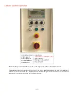
Page 15: ...gency Stop Button 9 Power Switch The turntable speed and load force knobs can be adjusted to achieve desired film tension The speed and load force work in conjunction If the table speed is increased t...

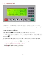
Page 16: ...ET button Use the left and right arrows to move the cursor to the value item to be changed Numeric values can be entered using the number pad or by scrolling through preset values using the up and dow...

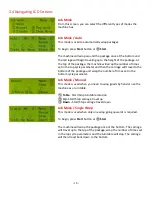
Page 17: ...of time in tenths of a second ie 15 1 5 seconds the carriage will continue upwards after the photo eye detects the top of the package Press SET enter the number of turntable rotations and press ENT Pa...

Page 18: ...ravel to the bottom of the package and wrap the number of times set in the bottom cycle parameter Job Mode Manual This mode is used when you need to wrap goods by hand or use the machine as a turntabl...

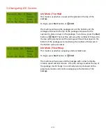
Page 19: ...ne will wrap the number of times set in the top cycle parameter and the carriage will travel back down to the bottom of the package were it will wrap the number of times set in the bottom cycle parame...

Page 20: ...of cycles and the total number of cycles of the machine To reset the current yield press the key Parameter Show This screen is used to view the current machine parameters Set Menu Language From the Ma...

Page 21: ...ord Press ESC until the Main Menu is displayed Press Password Press SET Enter your new password using the numeric keypad Press ENT Note For security reasons a random generated number will be displayed...

Page 22: ...words are displayed as 0 the new password has been set and can now be used How to Enter a Password Any time a menu item is selected that is password protected the Input Password screen will be display...

Page 23: ...reference 4 2 carriage maintenance Close door with a firm push Do Not slam or force If drive don t display rdy call tech support Machine will not stop at home Input signal 03 is not lit on PLC Bad co...

Page 24: ...e Adjust speed potentiometer to correct speed Film breaks Speed is not set well between load force and turntable speed adjust the settings Check for cuts in film Move dancer bar without film to see if...

Page 25: ...film from machine Step 3 Loosen jam nut Step 4 Loosen bolt in small increments to avoid damage to switch Step 5 Close carriage door gently Do not install stretch film Step 6 If the machine is able to...

Page 26: ...lt rated for lifting into the tapped hole in the turn plate Lift the turn table using a hoist and chain rated for a 500lb load See Fig 4 1 Lift the turntable just clear of the frame and use the forkli...

Page 27: ...bearing play If the diameter is less than 53mm or there is abnormal noise during operation replace the bad contact rollers See Fig 4 4 Name Part Number 1 Shrink Ring FG 03A 20 2 Core Holder Washer FG...

Page 28: ...in using the chain adjustment screw located at the back of the frame Fig 5 1 Table Chain Adjustment Loosen the four holding screws of the turntable motor using a 6mm Allen Wrench Turn the chain tensio...

Page 29: ...29 5 1 Illustration Base...

Page 30: ...G 12A 16 1 4 Ramp Bolt 1 5 Idler Wheel FG 01A 20 24 6 Turntable Gear FG 01A 13 1 7 Limit Switch N1CA2 1 8 Chain 12A 1 9 Base Frame n a 1 10 Tension Screw 91292A217 1 11 Motor Gear FG 01A 31 1 12 Motor...

Page 31: ...el Name Part Number Qty 1 Idler Wheel Bracket n a 12 2 Idler Wheel Axle FG 01A 24 12 3 Idler Outer Bushing FG 01A 23 24 4 Idler Bearing 60202 24 5 Idler Wheel FG 01A 21 24 6 Idler Wheel Snap Ring 9845...

Page 32: ...32 5 3 Illustration Mast...

Page 33: ...r FG 12 02 1 3 Upper Lower Limit Switch XCKP2145 2 4 Up Down Motor NMRV040 80 YS6344 1 5 Motor Axis FG 12 06 1 6 Chain 08B 2 7 Slide Rail FG AL 01 1 8 Up Down Shelf FG 12 04 1 9 Transition Shelf FG 12...

Page 34: ...34 5 4 Illustration Carriage...

Page 35: ...ing FG 152 1 14 Locating Pallet FG 2526 1 15 Roller Shaft FG 154 II 1 16 Retainer Ring FG 155 2 17 Anti Stretch Cover FG 157 1 18 Fixed Mount FG 165A 1 19 Micro Adjustable Block FG 168 1 20 Upper Bear...

Page 36: ...36 35 Transition Roller Inside Cover A50 2 36 Belt 40x55x3000 1...

Page 37: ...37 5 5 Illustration Film Roller Name Part Number Qty 1 E Clip 4 MM EC 2 2 2 Outer Tube Roll n a 1 3 Roller Bearing FG BR 02 2 4 Inner Shaft n a 1 5 Roller Assembly FG 08 07 1...

Page 38: ...38 5 6 Illustration Extended Roller Name Part Number Qty 1 E Clip 4 MM EC 2 2 2 Outer Tube Roll n a 1 3 Roller Bearing FG BR 02 2 4 Inner Shaft n a 1 5 Roller Assembly FG 08 07 1...

Page 39: ...39 5 6 Motor Controls...

Page 40: ...40 5 6 PLC Wiring...

Page 41: ...41 5 6 Switches Relays...

Reviews: