15
CAUTION!
Tighten ALL Assist Tower Bracket Bolts and Nuts.
Before removing the support straps or chain.
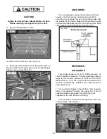
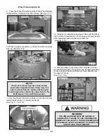
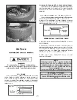
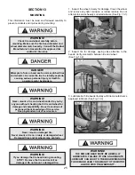
9. Remove lifting straps/ or chain.
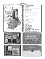
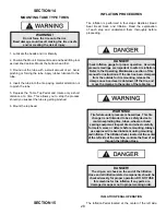
10. Remove the Side Panel. (See Fig. 8.16)
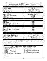
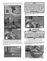
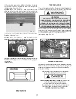
11. Route the Assist Tower Air Line through the hole on
the rear of the Tire Changer and connect to the Straight
Fitting as shown. (See Fig. 8.17)
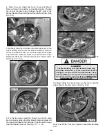
ANCHORING
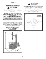
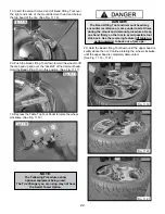
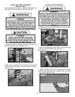
It is not essential to anchor the machine to the floor,
however, the floor must be smooth and level. When
anchoring to a concrete floor use the mounting holes that
are provided in the frame. Make sure the machine is solid
and level and supported evenly on all anchor points. Solid
shims may be used if necessary. (See Fig. 8.18)
SECTION 9
AIR SOURCE
This model requires a 14 to 15 CFM air source at
165 PSI maximum pressure. The safe operating pressure
range for this model is between 140 PSI and 165 PSI at
the machine. A 1/4” ID hose (or pipe) for connection to the
machine is satisfactory. Sufficient air pressure assures
good performance.
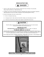
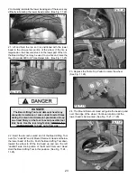
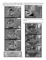
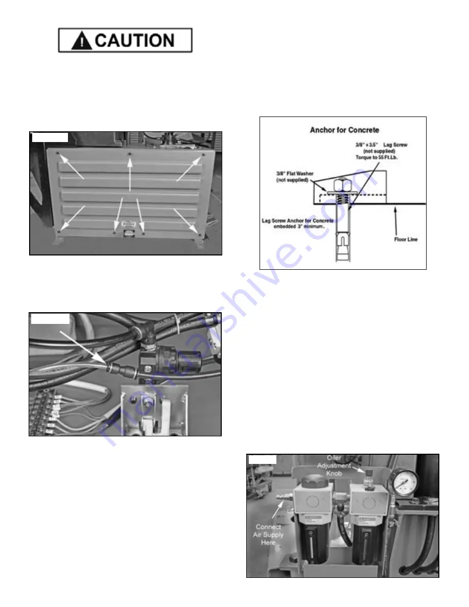
1. Connect the Air Supply to the Air Drier / Oiler. A proper
fitting (not supplied) to match the supply line of the air
supply connection is required. Use teflon tape (not
supplied) on the NPT thread of the fitting.
This connection is located on the right side of the rear
of the machine. (See Fig. 9.1)
Fig. 8.18
Fig. 9.1
Fig. 8.16
Fig. 8.17
Summary of Contents for R980X
Page 39: ...39 ...
Page 48: ...48 ...
Page 49: ...49 RECORD ALL MAINTENANCE NOTES AND SERVICE HISTORY HERE ...
Page 50: ...50 TIRE AND WHEEL DATA ...

