background image

Generating Device Labels

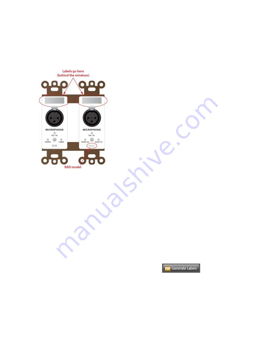
Most RADs (with the exception of the RAD16, AM1, and AM2) contain an area near its top in which
you can insert a custom label. We recommend that you use these labels to identify the channel asso-
ciated with the corresponding jack. The following graphic illustrates the placement of the labels:

To eliminate confusion and also streamline audio routing and troubleshooting, the channel names on the
physical RADs should match the channel names in Halogen. To help ensure this consistency, Halogen
includes a label generation feature that produces a PDF document of labels based on the channel names
you've entered in the software. We highly recommend that you use this feature to create your RAD
labels.

The timing of this label creation is up to you. It may be helpful to create the labels at the same time you
create the configuration file and insert them in the physical RADs (if they are available). If you label the
RADs early in the process, it may help the installers confirm that they are installing the right RADs in
the right places.

To generate RAD labels:

1. Within Halogen, open the configuration file from which you want to generate labels. Alter-

natively, if you have applied the configuration to a HAL device, you can open the device itself.

2. In the Hardware Workspace, confirm that the RADs are configured appropriately. At a mini-

mum, enter the names for the channels as this is needed for the generation of labels.

3. In the Hardware Workspace toolbar, click

Generate Labels

:

The

Gen-

erate Device Labels

dialog box displays.

4. In

Name and Location

, browse for or type the location and file name you want for the PDF file

you are generating. If you type the name of a folder that does not exist, the software will create
it for you. By default, the file is named

DeviceLabels.pdf

and is placed in

C:\Users\<user>\Documents\HalogenLabels,

although this location may

vary depending on your operating system.

CHAPTER 4:  Introduction to the Halogen Software

45

Summary of Contents for HAL1

Page 1: ...240 V 50 60 Hz 30 WATTS REMOTE AUDIO DEVICES DRS REMOTE AUDIO DEVICES 8 7 6 5 4 3 2 1 8 7 6 5 4 3 2 1 COMM POWER AUDIO TX AUDIO RX EXPANSION BUS LINK SHIELDED CAT 5e OR BETTER 24 VDC 100 mA This devi...

Page 2: ...by Rane 12 Use only with the cart stand tripod bracket or table specified by the manufacturer or sold with the apparatus When a cart is used use caution when moving the cart apparatus combination to a...

Page 3: ...d Processes 8 Using the HAL System Documentation 8 CHAPTER 2 Hardware Component Details 10 HAL1 Device 10 Rear Panel Description 11 Front Panel Description 13 Remote Audio Devices 15 How the CAT 5 Cab...

Page 4: ...Software 42 Uninstalling the Halogen Software 43 Upgrading Halogen Software and HAL Firmware 43 Generating Device Labels 45 Locating a Device 46 Swapping Hardware Devices 47 CHAPTER 5 Troubleshooting...

Page 5: ...minate the CAT 5 cabling first see Task 4 Pulling and Ter minating CAT 5 Cabling on page 30 so that the cables are ready to connect to the HAL For details on installing the HAL see Task 1 Install and...

Page 6: ...the installed equipment can successfully send and receive audio disregard this recommendation You will create a simple test configuration after you have installed all of the equipment Task 4 Pull and...

Page 7: ...eiving power if its data com munications connection is working and if its model matches the model configured for the port to which it is attached With a RAD you can also see if its transmit Tx and rec...

Page 8: ...L System includes both hardware and software components This system introduction provides a broad overview of these components Hardware Components The primary hardware component in a HAL System is the...

Page 9: ...e The ability to work in offline mode makes Hal ogen a powerful design tool available for use whether or not you have the hardware in hand And not only can you design your system without having hardwa...

Page 10: ...ation into a wall A DR1 requires a one gang switchbox while a DR2 and DR3 require two gang switchboxes Switchboxes used for both RADs and DRs must have a minimum depth of 2 1 4 57 mm Minimum Requireme...

Page 11: ...5 TCP Meter data NOTE Halogen and HAL might both use port 68 to communicate with a DHCP server This port is not actually used for communication between Halogen and HAL HAL devices send occasional UDP...

Page 12: ...tware It contains all the infor mation you need to work with the system There are several ways to access the Help System l Click the Help icon on the application toolbar Clicking the icon itself opens...

Page 13: ...d this guide on the Rane website as well as on the product DVD HAL System Installation Guide This guide the one you are reading is offered in both a PDF and hardcopy format and includes step by step i...

Page 14: ...evice is four times more powerful than the RPM88 Maximum Device Connections The device connections that are possible on a HAL1 are as follows l 4 Remote Audio Devices RADs l 8 Digital Remotes DRs Can...

Page 15: ...sover cable to connect to a computer or Ethernet switch The auto MDIX functionality takes care of coordinating the proper con nection between the devices The Ethernet LAN LED flashes when HAL detects...

Page 16: ...quate power to the DR port 8 Remote Audio Device LEDs Provides status information about the health of the CAT 5 connection between each RAD and HAL The numbers 1 through 4 correspond to the RAD ports...

Page 17: ...g l Overload LED red indicates that the mic line input is experiencing a signal overload l Signal LED green indicates the presence of an audio signal on the mic line input 2 Line Outputs LEDs Provides...

Page 18: ...r this port in the HAL configuration 5 The Ethernet Comm and Link LEDs Provides status information about the HAL Ethernet connection l Comm LED yellow flashes when HAL has been discovered by at least...

Page 19: ...AL also provides power to the RAD as well as a path for data communications Data communications makes it possible to control the RAD s configuration set tings view status information and update a RAD...

Page 20: ...RAD detects two things the communication pair of wires and that communication is established between the HAL and RAD The light dis plays solid red if the RAD cannot communicate with the HAL This is li...

Page 21: ...match the Power Comm Audio Tx and Audio Rx LEDs on the front of the corresponding RAD flash red Following is an illustration of the back and side of a typical RAD WARNING As it is poor design to plug...

Page 22: ...security The Pager1 also includes the following set of paging controls l A selectable list of available Paging Scenarios1 l Indicators for Busy Caution and Ready referring to the selected Scenario l T...

Page 23: ...ell as several additional program sources such as a laptop computer or a DVD player The Automixer 2 AM2 is a cascadable mixer that expands into the AM1 or other AM2s and increases the number of microp...

Page 24: ...ommunications link and power but no AES31 digital audio Because RAD ports contain all the functionality needed by a DR you can also connect DRs to RAD ports if for example all your DR ports are full a...

Page 25: ...te for Drag Net systems and how it was too wide to allow the mounting of two or more of them beside each other in a standard switch box You will be happy to know that the HAL System DRs can be mounted...

Page 26: ...channel to activate This behavior is similar to a radio button in a software application as displayed in the image below l List of Toggles Commands The control acts as a switch for enabling or disabl...

Page 27: ...e in a room l Single Level List of Toggles Commands This option allows you to control a single level and multiple other items For example you could use a DR3 to control the volume in a room as well as...

Page 28: ...ion Units connect to HAL via a FireWire1 expansion network which is similar to a USB cable and does not require IP addresses The only limitation when using FireWire is its maximum cable length of 15 f...

Page 29: ...screens there is no need to generate physical labels for them TIP If it s not possible to install CAT5 cabling in your installation but you want to use RAD functionality and or have more than 8 input...

Page 30: ...he HAL and EXP devices if applicable Working with DHCP Static IP Addresses and Routers Does your installation require the use of DHCP or static IP addresses Never fear it s as simple as can be But the...

Page 31: ...talling and Connecting HAL Expansion Units Installing and connecting an EXP device is simple Just as with the HAL device you can rely on the EXP s LED indicators to provide you with basic device and c...

Page 32: ...3 Configuring HAL Although listed as the third task in the installation process this task can occur later in the process if necessary To help with troubleshooting however we recommend loading the conf...

Page 33: ...the expected firmware version of the Halogen software the Connection Status is Available If the firmware version in the HAL is older than the version expected by Hal ogen the Connection Status is Dev...

Page 34: ...takes this limitation into consideration But it s important to double check that no CAT 5 cable you pull exceeds this distance l We recommend that you clearly label each end of each CAT 5 cable you in...

Page 35: ...the more recognized term of RJ45 The following graphic illustrates the T568 B termination and also shows the function of each wire pair on the HAL System network Task 5 Installing and Connecting RADs...

Page 36: ...hese LEDs corresponds to a twisted pair within the CAT 5 cable and a green light indicates that the twisted pair has been detected by the HAL and is working properly See Terminating the CAT 5 Cable on...

Page 37: ...The DR3 always dis plays Level and a level indicator in its level control unless it is configured as a List of Levels and there are no levels configured If configured as a List of Levels the list is...

Page 38: ...tes a problem with that specific twisted pair 5 When you are confident that a device is working properly you can attach it to the switchbox l If installing a RAD insert its label before attaching it t...

Page 39: ...r configured in the HAL for that port If the model numbers match the HAL sends the relevant configuration data as well as any required firmware updates to the RAD or DR If the model numbers do not mat...

Page 40: ...ion for the HAL Because you have installed a dif ferent RAD or DR model than was there before you will see a Device Mismatch error for the port on which this RAD or DR is connected You can either load...

Page 41: ...to do NOTE It s possible that some of the ports on the HAL have been configured for devices that will be connected sporadically for example RAD or DR devices on a rolling A V cart In this case you wi...

Page 42: ...y default are stored in the C Users username My Documents Halogen Configs folder You can save the file to a different location if desired however Creating a Verification Configuration Even if you do n...

Page 43: ...r We do recommend however that you check your RAD and DR installation against your drawings to confirm that they are in the correct locations In addition you can use the Locate functionality see Locat...

Page 44: ...ystem Halogen s easy to use graphical user interface simplifies the design and con figuration process so much that your only concern will be deciding how to use the extra time you suddenly have Basic...

Page 45: ...pace is a palette of objects on the left and a toolbar specific to the workspace To add an entity to your audio system you drag one or more objects from the palette to the workspace l The Hardware Wor...

Page 46: ...on the Rane web site 2 If downloading the software on the File Download box that appears click Run If you want to save the installation file to your computer click Save 3 When the download completes...

Page 47: ...ms Rane Corporation Halogen Uninstall Halogen 2 When prompted click Yes to confirm that you want to completely remove Halogen and all of its components A dialog box appears showing the status of the u...

Page 48: ...version of Halogen ensuring that you have the latest functionality available to you 2 Click the Update Firmware button to perform the update As part of the firmware update HAL also updates the firmwa...

Page 49: ...ysical RADs if they are available If you label the RADs early in the process it may help the installers confirm that they are installing the right RADs in the right places To generate RAD labels 1 Wit...

Page 50: ...ows you to verify the physical location of a specific HAL RAD DR or EXP When you place one of these devices in Locate mode from within the Halogen software the device hardware displays a signal which...

Page 51: ...gen and discover to your horror that there are mismatches in the Hardware Workspace You ve connected some of the RADs and or DRs to the wrong ports You installed the hardware in the right physical loc...

Page 52: ...rdware all references to it in the Proc essing Workspace are also deleted So you would in essence be starting over Instead you should swap devices to place them on their matching ports If necessary an...

Page 53: ...nd or network switch isn t powered on Power on both devices Patch cable or crossover cable is broken Try a different cable The port on the network switch isn t working Try plugging the cable into a di...

Page 54: ...r supply caus ing the error ON OFF OFF ON OFF The twisted pair in the CAT 5 cable that carries com munications data is wired incorrectly or broken Use a cable tester to verify the wiring of the CAT 5...

Page 55: ...rking Audio Rx will not work RAD Status Indicators Possible Causes Suggested Action Power Comm Audio Tx Audio Rx OFF OFF OFF OFF Room is dark and LEDs are off Shine a light on the RAD front panel The...

Page 56: ...ched assuming T568B termination GREEN GREEN RED GREEN The HAL is not receiving an audio stream from the RAD Use a cable tester to verify CAT 5 ter mination If using a punch block verify that the blue...

Page 57: ...l not supply power to the DR The CAT 5 cable between the DR and the HAL is too long Shorten the cable There is excessive voltage drop between the HAL and DR Verify it is 24 AWG or heavier cable Verify...

Page 58: ...lso indicate to Halogen that a HAL device is on the network so it can be displayed in the Connect to Device dialog box Lastly so that it can receive system status updates RaneLink II opens and maintai...

Page 59: ...running If not restart it Halogen employs a communications service called RaneLink II that helps control the connectivity with any HAL devices on the network RaneLink II is a communications applicatio...

Page 60: ...AL device will even appear in the Connect to Device dialog box Try power cycling the HAL and then running thBroadcastReceiver again 7 Verify that the correct network interface card NIC is being used I...

Page 61: ...ical Support 8 Ask your IT department for some assistance If your computer is administered by an IT department you may need their help Refer them to Required Ports on page 7 as well as Required Proces...

Page 62: ...ls generating 45 DHCP using with HAL 26 Digital Remotes See DRs Documentation overview 8 DRs available models 21 installing and connecting 31 LEDs 53 locating 46 overview 20 swapping 47 troubleshootin...

Page 63: ...L 28 installing and connecting EXP 27 installing Halogen 42 of HAL device 25 pulling terminating CAT 5 cabling 30 RADs and DRs 31 troubleshoot 36 workflow 1 Introduction to HAL System 4 IP addresses u...

Page 64: ...arting Halogen 42 Static IP addresses using with HAL 26 Swapping hardware devices 47 System requirements 6 T Technical support 57 Terminating CAT 5 cable 30 Troubleshooting DRs 53 HAL connection 54 HA...

Page 65: ...WARRANTY SHALL BE THAT WHICH IS DESCRIBED TO THE ORIGINAL RETAIL PURCHASER BY THE AUTHORIZED RANE DEALER OR DISTRIBUTOR AT THE TIME OF PURCHASE Rane Corporation does not however warrant its products a...

Page 66: ...FACTORY IN THE U S If the product is being sent to Rane for repair please call the factory for a Return Authorization number We recommend advance notice be given to the repair facility to avoid possi...

Page 67: ...tive The user of this equipment shall accept full responsibility for compliance with the LV directive and EMC directive in the event that the equipment is modified with out written consent of the manu...

Page 68: ...HAL System Installation Guide Rane Corporation 10802 47th Ave W Mukilteo WA 98275 5000 USA TEL 425 355 6000 FAX 425 347 7757 WEB rane com...

Reviews: