background image

Concepts and Features

R&S

®

 ZNC

88

User Manual 1173.9557.02 ─ 13

The power which the external power meter measured at the calibration plane is dis-
played in the calibration sweep diagram, together with the reference receiver reading.
The difference between the two traces is used to correct the reference receiver read-
ing, i.e. the reference receiver is calibrated by the external power meter results.

2.

Internal source power flatness calibration:

 In the following steps, the calibrated

reference receiver is used to adjust the source power. To this end, the R&S ZNC
performs a series of calibration sweeps at varying source power until the number of
"Total Readings" is reached or until the deviation between the calibrated reference
receiver power and the cal power is below a specified "Tolerance". The external
power meter is no longer used for these repeated calibration sweeps; everything is
based on the previously calibrated reference receiver. This speeds up the calibration
procedure but does not impair its accuracy.

3. After the flatness calibration, the R&S ZNC performs an additional verification sweep

in order to demonstrate the accuracy of the calibration.

After the source power calibration, one can expect the power at the calibration plane to
be within the range of uncertainty of the power meter. The reference receiver reading
corresponds to the calibrated source power. After a change of the sweep points or sweep
range, the analyzer interpolates or extrapolates the calibration data; see 

chapter 3.5.6.3,

"Power Calibration Labels"

, on page 89.

3.5.6.2

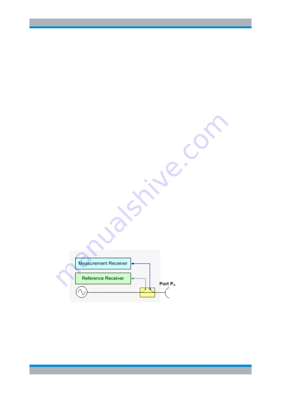
Measurement Receiver Calibration

A measurement receiver calibration ensures that the power readings at a specified
receive port of the analyzer (b-waves) agree with the source power level calibrated at an
arbitrary calibration plane. Typically, the calibration plane is at the input of the receiver
so that the calibration eliminates frequency response errors in the calibrated receiver.

In contrast, the reference receiver calibration, which is automatically performed together
with the (source) power calibration, ensures correct power readings for the generated
waves (a-waves).

A measurement receiver calibration generally improves the accuracy of power (wave
quantity) measurements. The correction data acquired in a frequency or power sweep is
re-used if a "Time" or "CW Mode" sweep is activated.


Calibration

Summary of Contents for ZNC3

Page 1: ...R S ZNC Vector Network Analyzers User Manual User Manual 2 1173 9557 02 13 Test Measurement...

Page 2: ...ery Rohde Schwarz would like to thank the open source community for their valuable contribution to embedded computing 2013 Rohde Schwarz GmbH Co KG M hldorfstr 15 81671 M nchen Germany Phone 49 89 41...

Page 3: ...the product The product is used for its designated purpose if it is used in accordance with its product documentation and within its performance limits see data sheet documentation the following safe...

Page 4: ...dangers Indicates a hazardous situation which if not avoided will result in death or serious injury Indicates a hazardous situation which if not avoided could result in death or serious injury Indicat...

Page 5: ...ot observed either at all or to the extent necessary electric shock fire and or serious personal injury or death may occur 1 Prior to switching on the product always ensure that the nominal voltage se...

Page 6: ...be fuse protected in such a way that anyone who has access to the product as well as the product itself is adequately protected from injury or damage 14 Use suitable overvoltage protection to ensure...

Page 7: ...masks and protective clothing must be worn 7 Laser products are given warning labels that are standardized according to their laser class Lasers can cause biological harm due to the properties of the...

Page 8: ...n permitted 5 If a cell develops a leak the fluid must not be allowed to come into contact with the skin or eyes If contact occurs wash the affected area with plenty of water and seek medical aid 6 Im...

Page 9: ...s substances or fuels can cause health problems and lead to environmental damage For additional information about environmental protection visit the Rohde Schwarz website Instrucciones de seguridad el...

Page 10: ...el uso del producto Deber n tenerse en cuenta todas las dem s informaciones de seguridad como p ej las referentes a la protecci n de personas que encontrar n en el cap tulo correspondiente de la docu...

Page 11: ...l producto se emplea de forma sin nima el t rmino CUIDADO Las palabras de se al corresponden a la definici n habitual para aplicaciones civiles en el rea econ mica europea Pueden existir definiciones...

Page 12: ...la tensi n preseleccionada en el producto coincida con la de la red de alimentaci n el ctrica Si es necesario modificar el ajuste de tensi n tambi n se deber n cambiar en caso dado los fusibles corre...

Page 13: ...efectuadas por un electricista especializado 13 En el caso de dispositivos fijos que no est n provistos de fusibles interruptor autom tico ni otros mecanismos de seguridad similares el circuito de ali...

Page 14: ...empresario operador tiene la obligaci n de evaluar y se alizar las reas de trabajo en las que exista un riesgo elevado de exposici n a radiaciones 6 Tenga en cuenta que en caso de incendio pueden desp...

Page 15: ...r ni fuego Debe evitarse el almacenamiento a la luz directa del sol Las celdas y bater as deben mantenerse limpias y secas Limpiar las conexiones sucias con un pa o seco y limpio 3 Las celdas o bater...

Page 16: ...vos el ctricos usados no se deben desechar con los residuos dom sticos sin clasificar sino que deben ser recogidos por separado Rohde Schwarz GmbH Co KG ha elaborado un concepto de eliminaci n de resi...

Page 17: ...ed for exam ple according to the ISO9001 and ISO14001 management systems Environmental commitment Energy efficient products Continuous improvement in environmental sustainability ISO14001 certified en...

Page 18: ...ument up to date and to be informed about new application notes related to your instrument please send an e mail to the Customer Support Center stating your instrument and your wish We will take care...

Page 19: ...Control 14 3 1 5 Data Flow 17 3 2 Screen Elements 19 3 2 1 Control Elements of the Screen 19 3 2 2 Display Elements in the Diagram 24 3 2 3 Dialogs 34 3 2 4 Display Formats and Diagram Types 35 3 3 Me...

Page 20: ...rsal Interface R S ZN B14 103 3 7 4 Extended Power Range 103 3 7 5 External Power Meters 104 4 GUI Reference 106 4 1 File Settings 106 4 1 1 File Recall Sets 106 4 1 2 File Print 109 4 1 3 File Trace...

Page 21: ...308 4 6 3 Info Dialog 314 4 6 4 Service Function Dialog 316 4 6 5 System Setup Freq Ref 316 4 6 6 System Setup Remote Settings 317 4 6 7 Remote LXI Dialog 320 4 6 8 System Setup External Devices 321...

Page 22: ...ment Hardware 347 5 4 4 Status Reporting System 347 5 4 5 Output Unit 348 5 4 6 Command Sequence and Command Synchronization 348 5 5 Status Reporting System 349 5 5 1 Overview of Status Registers 350...

Page 23: ...nds 531 6 3 14 SENSe Commands 534 6 3 15 SOURce Commands 619 6 3 16 STATus Commands 645 6 3 17 SYSTem Commands 648 6 3 18 TRACe Commands 670 6 3 19 TRIGger Commands 673 6 4 R S ZVR ZVAB Compatible Com...

Page 24: ...irmware Installation Update 735 9 Annexes 737 9 1 Interfaces and Connectors 737 9 1 1 Rear Panel Connectors 737 9 1 2 LAN Interface 739 9 1 3 GPIB Interface 739 9 1 4 Universal Interface 742 9 2 Maint...

Page 25: ...nd reference information for manual and remote control The User Manual is available on the documentation CD ROM the most recent version is available for download on the R S ZNC product pages on the R...

Page 26: ...Manual 1173 9557 02 13 2 Release Notes for Firmware V1 81 Version V1 81 of the R S ZNC firmware provides the following changes Bug fix Missing Channel Bits in Segmented sweeps Software version To chec...

Page 27: ...esources are easily accessible and that user defined configurations can be conveniently imple mented stored and reused the instrument uses a hierarchy of structures Global resources can be used for al...

Page 28: ...traces in the diagrams The channel settings for all channels associated to the traces The display settings for each diagram The File menu is used to organize recall sets 3 1 3 Traces Channels and Diag...

Page 29: ...of the Channel menu Each trace is assigned to a channel The channel settings apply to all traces of the channel If a trace is selected in order to apply the trace settings it becomes the active trace...

Page 30: ...t the bottom of the diagram together with the Stimulus values and the display colors of all traces The active channel is highlighted Ch1 in the example below Tapping a trace in the trace list selects...

Page 31: ...e settings In particular a fixed source port and receive port is used Each sweep point requires a single partial measurement See also chapter 3 3 1 S Parameters on page 43 For a complete two port S pa...

Page 32: ...Sweep Trigger event starts n partial sweeps over all sweep points Trigger event starts m complete measurements at consecutive sweep points Sweep Segment Trigger event starts n partial sweeps over the...

Page 33: ...le at the cali brated reference plane CW Mode The stimulus keys define the fixed stimulus frequency CW Frequency of the mea surement The other sweep parameters e g the Number of Points are set via CHA...

Page 34: ...Concepts and Features R S ZNC 18 User Manual 1173 9557 02 13 Basic Concepts...

Page 35: ...of the analyzer provides all control elements for the measurements and contains the diagrams for the results There are several alternative ways for accessing an instrument function Using the icons in...

Page 36: ...rol elements of the user interface All controls are also accessible from the R S ZNC s softtool panels The toolbar is divided into two parts The icons in the left part initiate frequently used actions...

Page 37: ...A button with three dots e g User Define in the example above opens a dialog which provides several related settings A button with a checkmark e g Frequency Info in the example above enables or disab...

Page 38: ...at can be used to return to a defined instru ment state reverse operations access service functions and define various system related settings The Help menu provides assistance with the network analyz...

Page 39: ...icularly useful if the analyzer is controlled from an external monitor or Remote Desktop Alternatively the settings are accessible from the menu bar or from the context menus The hardkey panel is hidd...

Page 40: ...s Diagrams are independent of trace and channel settings A diagram can contain a practically unlimited number of traces which may be assigned to different channels Most diagram settings are arranged i...

Page 41: ...ints displayed together in the diagram The individual data points are connected so that each trace forms a continuous line The trace can be complemented by the following display elements plotted with...

Page 42: ...t is possible to generate an unlimited number of memory traces from a data trace and display them together Markers and marker functions are available for all trace types The trace type of each trace i...

Page 43: ...traces Tap and hold any of the sections in the trace list except the type section to open a context menu and access the most common tasks related to the section Example The following context menu is...

Page 44: ...the trace Marker Search Target Search Bandfilter Search Activating and Moving Markers To select one of several markers as an active marker do one of the following Tap the marker symbol Tap the marker...

Page 45: ...ge the position appearance or contents of the marker info field use one of the following methods Tap and hold the info field to open a context menu providing frequently used marker settings The info f...

Page 46: ...g is released The remaining markers on the other traces become slave markers and are moved to the position of the corresponding master markers Missing slave markers are cre ated so that each trace has...

Page 47: ...characteristic filter parameters Bandpass and bandstop regions can be described with the same parameter set A bandpass region contains a local maximum around which the magnitude of the trace falls of...

Page 48: ...ist below the diagram Each line in the channel list describes a single channel The channel of the active trace is highlighted The lines are divided into several sections with the following contents fr...

Page 49: ...ings in the context menus correspond to the most common functions in the CHANNEL CONFIG Channels STIMULUS CHANNEL SWEEP Sweep Par ams and CHANNEL POWER BW AVG menus 3 2 2 5 Context Menus To provide ac...

Page 50: ...ts behind their labeling as in Balanced Ports call up a dialog The dialogs of the analyzer have an analogous structure and a number of common control elements Dialogs are controlled in the usual way F...

Page 51: ...r all display formats involving a conver sion of the measurement data into a real scalar quantity i e for dB Mag Phase Delay SWR Lin Mag Real Imag and Unwrapped Phase Polar diagrams are used for the d...

Page 52: ...from the measured data by non linear conversions The following examples show the same trace in Cartesian diagrams with linear and log arithmic x axis scaling 3 2 4 2 Conversion of Complex into Real Q...

Page 53: ...omplex plane with a horizontal real axis and a vertical imaginary axis The grid lines correspond to points of equal magnitude and phase The magnitude of the response values corresponds to their distan...

Page 54: ...sistance and reactance Points with the same resistance are located on circles Points with the same reactance produce arcs The following example shows a Smith chart with a marker used to display the st...

Page 55: ...nd neg ative capacitive reactive components of the impedance respectively Example Reflection coefficients in the Smith chart If the measured quantity is a complex reflection coefficient e g S11 S22 th...

Page 56: ...of an open circuit Z infinity I 0 is one its phase is zero The magnitude of the reflection coefficient of a short circuit Z 0 U 0 is one its phase is 180 deg 3 2 4 5 Inverted Smith Chart The inverted...

Page 57: ...ersection points between the hor izontal axis and the outer circle the admittance is infinity short and zero open The outer circle corresponds to zero conductance purely imaginary admittance Points ou...

Page 58: ...itude of the reflection coefficient of an open circuit Y 0 I 0 is one its phase is zero 3 2 4 6 Measured Quantities and Display Formats The analyzer allows any combination of a display format and a me...

Page 59: ...transmission coefficients Sij The default formats are activated automatically when the measured quantity is changed 3 3 Measurement Results This section gives an overview of the measurement results of...

Page 60: ...denote the output and input port numbers of the DUT Meaning of 2 port S parameters The four 2 port S parameters can be interpreted as follows S11 is the input reflection coefficient defined as the rat...

Page 61: ...ance parameter is obtained from a single S parameter Z parameters complete description of the n port DUT 3 3 2 1 Converted Impedances The converted impedance parameters describe the input impedances o...

Page 62: ...ential mode input impedance at port 4 of a DUT that is terminated at its other ports with the reference impedance Z0 You can also read the converted impedances in a reflection coefficient measurement...

Page 63: ...e easily extended to describe circuits with more than two ports or several modes of propagation 3 3 3 Admittance Parameters An admittance is the complex ratio between a current and a voltage The analy...

Page 64: ...s to S parameters Ydd22 is the differential mode input admittance at port 2 of a DUT that is terminated at its other ports with the reference impedance Z0 You can also read the converted admittances i...

Page 65: ...tended to describe circuits with more than two ports or several modes of propagation 3 3 4 Wave Quantities and Ratios The elements of the S Z and Y matrices represent fixed ratios of complex wave ampl...

Page 66: ...es includes the direction and the test port number Addi tionally the source port must be specified The letter a indicates a transmitted wave b a received wave Examples a1 Src Port 1 is the outgoing wa...

Page 67: ...ates an outgoing wave b an incoming wave Examples b2 a1 Src Port 1 is the ratio of the outgoing wave b2 at port 2 and the incident wave a1 at port 1 this corresponds to the S parameter S21 forward tra...

Page 68: ...denominator individually and using the trace functions A possible application is the comparison of different detector settings for a particular trace Error Messages The analyzer generates a warning if...

Page 69: ...d Moreover it is possible to assign arbitrary inde pendent reference impedance values to each unbalanced port and to the differential and common mode of each logical port The following types of balanc...

Page 70: ...ers can be interpreted as follows S mout min 11 is the mixed mode input reflection coefficient defined as the ratio of the wave quantities b1 mode mout to a1 mode min measured at PORT 1 forward measur...

Page 71: ...ls with equal amplitude and opposite phase appear at the phys ical ports m and n This means that the ratio Skm Skn of the physical transmission coefficients of an ideal balun equals 1 This ratio is ca...

Page 72: ...The default values for the balanced port reference impedances are derived from the default reference impedance of the physical analyzer ports Z0 50 The default value for the differential mode is Z0d...

Page 73: ...waves In the model of Kurokawa Power Waves and the Scattering Matrix the wave quantities a and b are transformed as follows i i i i i i i i i i i i i i b a Z Z Z Z Z Z Z Z Z Z b a 0 0 1 0 1 0 1 0 1 0...

Page 74: ...alent to unconditional sta bility This means that 1 and 2 provide direct insight into the degree of stability or potential instability of linear circuits References Marion Lee Edwards and Jeffrey H Si...

Page 75: ...ferent file formats 3 4 1 Limit Check A limit line is a set of data to specify the allowed range for some or all points of a trace Typically limit lines are used to check whether a DUT conforms to the...

Page 76: ...Start Stimu lus value of segment no n 1 Overlapping segments are allowed The limit check in the overlapping area is related to the tighter limit the pass test involves a logical AND operation Gaps bet...

Page 77: ...n the segments are minimized To facilitate the interpretation the R S ZNC displays only the limit line segments which provides the limit check criterion the tighter limit line at each point In the exa...

Page 78: ...ely outside the sweep range however the limits are only checked at the measurement points The following figure shows a ripple limit test involving 3 active ranges The limit line rules for logarithmic...

Page 79: ...e admittance Im Y susceptance falls below a limit 3 4 1 4 File Format for Limit Lines The analyzer uses a simple ASCII format to export limit line data By default the limit line file has the extension...

Page 80: ...owing lines contain the entries of all editable columns of the list Example of a ripple limit file The ripple limit list is described by the ripple limit file Compatibility with other instruments Netw...

Page 81: ...r documentation of the trace data file Any number of comment lines may be inserted before or after the header line The trace data section corresponds to a set of single ended S parameters It depends o...

Page 82: ...2 S parameters must be available Export of system error corrected incomplete S parameter sets is possible too If the port configuration con tains balanced ports the Touchstone file will contain the c...

Page 83: ...Best File Format The file format depends on how you want to use the exported data Use a Touchstone file format to export single ended S parameter data traces to a file that can be evaluated with appli...

Page 84: ...ration standards available Due to the analyzer s calibration wizard calibration is a straightforward menu guided process Moreover it is possible to perform the entire calibration process automatically...

Page 85: ...Match1 S11 or S22 Reflection tracking Source match Directivity High Reflection measure ments on any port One Path Two Ports Open Short Match1 at source port Through2 S11 S21 or S22 Reflection tracking...

Page 86: ...e declared to be Open Short and Match irrespective of their properties 2 Or any other known two port standard See remark above The calibration type must be selected in accordance with the test setup S...

Page 87: ...ovides the transmission tracking error term A one path two port calibration requires only four standards to be connected instead of 7 for a full two port TOSM calibration It is suitable when only the...

Page 88: ...ugh the analyzer auto matically determines its delay time transmission phase 3 5 1 5 TOM Calibration A TOM Through Open Match calibration requires a low reflection low loss Through standard with an el...

Page 89: ...if the phase shift resulting from the electric length difference between the Through and the Line standard is between 20 and 160 This corresponds to a ratio of 1 8 for the start and stop frequency of...

Page 90: ...ed up to a frequency flong where its transmission phase is equal to 160 deg This frequency is equal to flong 4 c0 9 llong lthr The shorter Line can be used from a frequency fshort where its transmissi...

Page 91: ...twork Attenuation calibration requires two port standards only Again the Through standard must be ideally matched and lossless The Symmetric Net work must have the same properties as the Reflect stand...

Page 92: ...Short circuit one port 0 Offset short Short circuit with added electrical length offset for waveguide calibration one port 0 Match Matched broadband termination one port Z0 characteristic impedance of...

Page 93: ...a for one port standards has an additional factor on the right hand side The reason for this factor is that the Loss in dB accounts for the attenuation along the forward and the reverse path no matter...

Page 94: ...ation kits of the model Typical parameters labeled typical approximately describe a calibration kit model To correct for deviations between the standards each kit of the model is individually measured...

Page 95: ...nes and further corrects this match point following I K sa s circle fitting algorithm To obtain the reflection coefficient for a perfectly matched calibration standard the Sliding Match must be measur...

Page 96: ...n kit file format The files must be converted using an R S ZVR network analyzer equipped with a firmware version V3 52 or higher Proceed as follows On the R S ZVR press CAL CAL KITS MODIFY KITS INSTAL...

Page 97: ...at shall be restored after a user defined preset If a new channel is created the channel calibration of the active channel is also applied to the new channel See also Calibration Labels 3 5 4 Calibrat...

Page 98: ...f 4 1164 0521 30 R S ZV Z53 300 kHz to 18 GHz type N f 2 1164 0473 72 R S ZV Z53 300 kHz to 24 GHz 3 5 mm f 2 1164 0473 32 R S ZV Z54 10 MHz to 40 GHz 2 92 mm f 2 1164 0467 92 R S ZV Z55 10 MHz to 50...

Page 99: ...units provide the following connectors A USB type B connector at the rear is used to power supply and control the unit A USB cable for connection to the network analyzer is provided with the calibrat...

Page 100: ...connect or disconnect the unit while data is being transferred between the analyzer and the unit Never connect the unit during a firmware update 3 5 5 2 Performing an Automatic Calibration After conne...

Page 101: ...d on the number of ports For a single calibrated port the reflection calibration types are available Refl Norm Open Refl Norm Short Refl OSM For 2 ports the analyzer provides the following additional...

Page 102: ...ll calibrated ports Trans Norm Both Trans Norm Forward One Path Two Ports OSM CalPort 1 OSM CalPort2 all calibrated ports Through between all pairs of ports 3 5 6 Scalar Power Calibration The purpose...

Page 103: ...al application for a power calibration in a frequency sweep is the measurement of the gain of an amplifier across a frequency range but at a fixed input power In a power sweep the power calibration en...

Page 104: ...tional verification sweep in order to demonstrate the accuracy of the calibration After the source power calibration one can expect the power at the calibration plane to be within the range of uncerta...

Page 105: ...lyzer interpolates or extrapolates the calibration data 3 5 6 3 Power Calibration Labels Power calibration labels in the trace list for wave quantities and ratios inform you about the status and type...

Page 106: ...polate power correction data so that a source or receiver power calibration can be reused after a change of the frequency sweep range At new sweep points within the calibrated sweep range interpolatio...

Page 107: ...calibration Test and measurement procedure 1 Perform the calibration with the additional two port between the analyzer port and the power sensor During the calibration the analyzer increases the power...

Page 108: ...tab Electrical Length Mechanical Length or Delay are coupled parameters When one of them is changed the other two follow For a non dispersive DUT the delay defined above is constant over the consider...

Page 109: ...ength The delay is displayed in the CHANNEL OFFSET EMBED Offset Auto Length tab The cable length depending on the velocity factor can be read in the Mechanical Length field It is also possible to dete...

Page 110: ...oss function CHANNEL OFFSET EMBED One Way Loss Auto Length and Loss determines all offset parameters such that the residual group delay of the active trace defined as the negative derivative of the ph...

Page 111: ...must be assigned to both physical ports that are combined to form the logical port If different offset parameters have been assigned to the physical ports before they are both corrected by the same am...

Page 112: ...the DUT If you observe this effect an Open and Short compensation may improve the accuracy Open and Short compensation is more time consuming because it requires two con secutive fixture compensation...

Page 113: ...ses a positive phase shift of the measured parameter and therefore reduces the calculated group delay A negative offset parameter causes a negative phase shift of the measured param eter and therefore...

Page 114: ...rox a factor of 2 This increased computation time is usually negligible compared to the sweep times of the analyzer The following properties of the Chirp z transformation are relevant for the analyzer...

Page 115: ...sponses The impulse response corresponds to the response of a DUT that is stimulated with a short pulse The step response corresponds to the response of a DUT that is stimulated with a voltage wavefor...

Page 116: ...and the additional condition that f1 f In other words all frequencies fi are set to harmonics of the start frequency f1 If a harmonic grid including the DC value f 0 is mirrored to the negative frequ...

Page 117: ...rids can not be calculated for any set of sweep points If the minimum number of sweep points is smaller than 5 then the interpolation extrapolation algorithm for additional sweep points will not work...

Page 118: ...s on amplitude accuracy are low Steep Edges Hamming 43 dB 0 019 dB Good compromise between edge steepness and sidelobe suppression Normal Gate Hann 32 dB 0 032 dB Good compromise between edge steepnes...

Page 119: ...C 625 The GPIB interface is mostly intended for remote control purposes and for the connection of external devices e g power meters For details refer to chapter 9 1 3 GPIB Interface on page 739 3 7 3...

Page 120: ...urement with an unknown LO signal and therefore unknown IF output fre quency Power calibration An external power meter can measure the exact signal power at an arbitrary point in the test setup refere...

Page 121: ...n error message Zeroing can take a few seconds depending on the power meter model refer to the documentation of your external power meter for more information Repeat zeroing During warm up after switc...

Page 122: ...1 File Settings The File menu provides standard Windows functions to create save recall or print recall sets to copy the active screen and to shut down the application 4 1 1 File Recall Sets A recall...

Page 123: ...ecall dialog Specifies the name and location of a particular file e g a VNA recall set file to open Look in specifies the drive and directory in which the file to open is stored The icons to the right...

Page 124: ...e field Files of type selects a particular file type e g recall set files znx for the created file Save saves the data e g the active recall set in the selected file and directory and closes the dialo...

Page 125: ...key or Ctrl P Print Printer Prints the active recall set using the current printer and printer settings Remote command The HCOPy commands provide the printer settings see chapter 6 3 7 HCOPy Commands...

Page 126: ...can be installed using the Start Control Panel Hardware and Sound Devi ces and Printers menu in the Windows Control Panel Remote command The HCOPy commands provide the printer settings see chapter 6 3...

Page 127: ...s previously stored trace data into the active diagram The analyzer opens a dialog box to select the file from all trace files s p csv dat stored on the file system see Recall dialog The opened trace...

Page 128: ...r a detailed description of all measurement results of the R S ZNC refer to chapter 3 3 Measurement Results on page 43 Efficient trace handling To select a result and display it as a trace you can sim...

Page 129: ...ckground information see chapter 3 3 1 S Parameters on page 43 Single ended unbalanced S parameters are referred to as S out in where out and in denote the output and input logical port numbers respec...

Page 130: ...s for an n port vector network analyzer and displays the full set of S parameters one in each diagram The diagrams are arranged as an n x n matrix The reflection coefficients Sii appear in the diagram...

Page 131: ...f the physical analyzer ports is Z0 50 The default reference impedances for balanced ports are derived hereof You do not need to change these value unless you want to renormalize the port impedances s...

Page 132: ...for active DUTs ensure no compression if an active DUT with 20 dB or 40 dB gain is measured If the actual gain of the DUT is more than 50 dB then the default source power of 40 dB is still too high a...

Page 133: ...me it is recommended to specify the ports that are not used in the current test setup as Unused ports Unused ports will not be con sidered for the calculation of mixed mode Z and Y parameters Backgrou...

Page 134: ...mber is assigned Select Predefined List of predefined port configurations Three configurations are possible Two single ended ports one balanced port only one port uses single ended reflection measurem...

Page 135: ...Balanced and Measured Ports dialog re defines the port impedances for differential and common mode Background information Refer to chapter 3 3 5 4 Reference Impedances on page 56 Access E g TRACE MEAS...

Page 136: ...e physical analyzer ports Z0 50 The default value for the differential mode is Z0d 100 2 Z0 The default value for the common mode is Z0c 25 Z0 2 Remote command SOURce Ch LPORt LogPt SENSe Ch LPORt Log...

Page 137: ...coefficient b2 a1 Source Port 1 is the ratio of the wave quantities b2 and a1 and corresponds to the S parameter S21 forward transmission coefficient b2 a2 Source Port 2 is the ratio of the wave quant...

Page 138: ...cess TRACE MEAS Ratios More Ratios The notation for ratios follows the usual scheme of the vector network analyzer The a waves are the outgoing transmitted waves at the analyzer s test ports The b wav...

Page 139: ...new trace and select trace name and measurement parameter CALCulate Ch PARameter SDEFine Trace_Name Ratio the parameter name Ratio can also contain the source port Detector Selects the algorithm that...

Page 140: ...rd S parameter measurement this is the reflected wave at port 1 of the DUT forward measurement b2 Source Port 1 is the wave received at test port 2 In a standard S parameter measurement this wave is t...

Page 141: ...ties dialog provides arbitrary wave quantities with arbitrary source ports as measured quantities All wave quantities can be calculated with different detector settings Background information Refer to...

Page 142: ...ce_Name A1 the parameter name Ratio can also contain the source port Show as Selects the physical unit of the displayed trace It is possible to display the measured Voltage V or convert the wave quant...

Page 143: ...Name Z S11 Z S12 Create new trace and select trace name and measurement parameter CALCulate Ch PARameter SDEFine Trace_Name Z S11 Z S22 Z S11 Z S12 Z S21 Z S22 Selects the 2 port converted impedance p...

Page 144: ...Z S21 Z S22 Balanced Ports Opens a dialog to define a balanced port configuration See chapter 4 2 1 3 Balanced Ports Dialog on page 116 4 2 1 9 Meas Y Sij Selects converted admittances as measured qua...

Page 145: ...at is terminated at port 1 with the reference impedance Z0 matched circuit admittance measured in a reverse reflection measurement Y12 and Y21 denote the forward and reverse converted transfer admitta...

Page 146: ...eters are expressed as Y Z out in where out and in denote the output and input port numbers of the DUT Remote command CALCulate Ch PARameter MEASure Trace_Name Y11 Z11 Create new trace and select trac...

Page 147: ...0 The four 2 port Z parameters can be interpreted as follows Z11 is the input impedance defined as the ratio of the voltage V1 to the current I1 measured at port 1 forward measurement with open output...

Page 148: ...s Imbalance parameters are expressed as Imb out in where out and in denote the logical output and input port numbers of the DUT Remote command CALCulate Ch PARameter MEASure Trace_Name IMB21 IMB12 Cre...

Page 149: ...A Stability Selects a stability parameter as a measured quantity for the active trace The stability factor calculation is based on 2 port reflection and transmission S parameters so that the input an...

Page 150: ...er SDEFine Trace_Name MUF121 MUF221 KFAC21 Balanced Ports Opens a dialog to define a balanced port configuration See chapter 4 2 1 3 Balanced Ports Dialog on page 116 4 2 1 13 Meas Power Sensor Opens...

Page 151: ...Ch PARameter MEASure TraceName PmtrD1 CALCulate Ch PARameter SDEFine TraceName PmtrD1 Auto Zero Initiates an automatic zeroing procedure of the power meter which must be disconnected from the RF power...

Page 152: ...e for measurements related to power ratios insertion loss gain etc Tip alternative formats The magnitude of each complex quantity can be displayed on a linear scale It is possible to view the real and...

Page 153: ...of any measurement point dB values for the magnitude and other conversions can be obtained by means of the Marker Format functions Remote command CALCulate Chn FORMat SMITh Polar Selects a polar diag...

Page 154: ...compensate for this effect in the measurement results To compensate for a frequency dependent delay in the test setup a system error correction is required Note The delay for reflection factors corres...

Page 155: ...the noise in the group delay a large aperture tends to minimize the effects of noise and phase uncertainty but at the expense of frequency resolution Phase distortions i e deviations from linear phas...

Page 156: ...R Lin Mag Selects a Cartesian diagram with a linear vertical axis scale to display the magnitude of the measured quantity Properties The stimulus variable appears on the horizontal axis scaled linearl...

Page 157: ...mmand CALCulate Chn FORMat REAL Imag Selects a Cartesian diagram to display the imaginary part of a complex measured quan tity Properties The stimulus variable appears on the horizontal axis scaled li...

Page 158: ...atible with the current display format are unavailable grayed Relations between the scaling parameters The scaling parameters Scale Div Ref Value Ref Position Max Min are coupled together in the follo...

Page 159: ...r See Ref Val Max Min Marker on page 209 Zoom Active Enables or disables the current scale settings including all the numeric entries in the input fields below See also Using the Graphic Zoom in the R...

Page 160: ...ef Position is varied the value of the reference line Ref Value is left unchanged so the current trace is shifted together with the Ref Position Ref Position is not available grayed for polar diagrams...

Page 161: ...traces Remote command n a 4 2 3 3 Scale Zoom Provides the graphical and numerical zoom functions A zoom magnifies a rectangular portion inside a diagram zoom window to fill the entire diagram area Alt...

Page 162: ...th an additional overview window The overview window appears in the upper part of the active diagram and shows the original diagram and the zoom area You can move the zoomed part of the trace by movin...

Page 163: ...ain an active trace The active remote traces and the active manual trace are independent of each other see chapter 5 3 2 Active Traces in Remote Control on page 343 Access TRACE SCALE key or Alt Shift...

Page 164: ...ace and channel settings of the former active trace but displayed with another color The new trace is named Trc n where n is the largest of all existing trace numbers plus one The name can be changed...

Page 165: ...indicates the channel of each trace Area indicates the diagram area of each trace Scale shows which traces use common scaling and format settings Rules for trace names The analyzer can define mathema...

Page 166: ...ger dialog Couple All assigns all traces to the channel or scale settings of the active trace All channel or scale settings except the selected ones are lost The analyzer displays a confirmation dialo...

Page 167: ...memory and performs mathematical operations on traces Background information Refer to Trace Types on page 26 Access TRACE SCALE key or Alt Shift D Destination Shows the available memory traces Some o...

Page 168: ...d trace settings from the data trace The following display settings of a data trace and the associated memory traces are fully coupled Changing a property of one trace affects the properties of all ot...

Page 169: ...mathematical trace Math is dis played in the trace list while the mathematical mode is active Trace Math is enabled if the active data trace fulfils the conditions for evaluating the mathematical rela...

Page 170: ...ctive trace is replaced by the corresponding point of the mathematical trace Compatibility between traces in mathematical relations Mathematical traces are either constant functions or functions of on...

Page 171: ...in abbreviated form e g 2e for 2 e The Clear Del Back buttons are used to correct faulty entries Check performs a consistency check of the displayed mathematical expression and displays a message Oper...

Page 172: ...be set in the Balanced Ports dialog In time sweeps StimVal is the stimulus time in s In CW mode sweeps StimVal is the number of the point Remote command CALCulate Chn MATH WUNit STATe Result is Wave Q...

Page 173: ...athematical trace value amounts to 1 real value the port impedance is 50 If Result is Wave Quantity is on the analyzer assumes the trace value to be 1 V which is converted into a linear power of 20 mW...

Page 174: ...he current state of the active data traces modified by the trace functions to mem ory traces in accordance with the Destination setting Trace functions The trace functions comprise the following mathe...

Page 175: ...e a trace that was unintentionally deleted Remote command CALCulate Ch PARameter DELete 4 2 4 7 Trace Config Time Domain Calculates and displays the results as a function of time The functionality is...

Page 176: ...in the frequency domain are coupled with each other The analyzer places no restriction on the measured quantities to be transformed into the time domain Impedances and admittances are first converted...

Page 177: ...Hebyshev Resolution Enh ancement Broadens the frequency range that the analyzer considers for the time domain transform by a linear factor A factor of 1 means that the original sweep range and the mea...

Page 178: ...p remains approximately the same This may increase the sweep time due to the additional sweep points introduced The three grids can be calculated repeatedly in any order the analyzer always starts fro...

Page 179: ...tional input The extrapolation is repeated after each sweep Remote command CALCulate Chn TRANsform TIME LPASs DCSParam CALCulate Chn TRANsform TIME LPASs DCSParam CONTinuous CALCulate Chn TRANsform TI...

Page 180: ...where f is the spacing between two consecutive frequency points Simply reduce the time span until the warning disappears Remote command CALCulate Chn FILTer GATE TIME CENTer CALCulate Chn FILTer GATE...

Page 181: ...NC always uses a Steepest Edges Rectangle window to calculate the time gated frequency domain trace see Time Gated Frequency Domain Trace on page 102 See also chapter 3 7 1 5 Time Gates on page 102 Re...

Page 182: ...est of all response values yi Pk Pk is the peak to peak value and is equal to the difference Max Min Mean is the arithmetic mean value of all response values n i i y n Mean 1 1 SDev is the standard de...

Page 183: ...frequency in the selected evaluation range Delay is the phase delay which is an approximation to the group delay and calcu lated as follows f PD deg 360 where f is the width of the evaluation range a...

Page 184: ...Displays or hides all results related to the x dB compression point of the trace where x is the selected compression value To obtain valid compression point results a power sweep must be active and th...

Page 185: ...ults if the wrong sweep type or trace format is selected or if the trace contains no x dB compression points in the selected evaluation range Remote command CALCulate Chn STATistics NLINear COMP STATe...

Page 186: ...log on page 199 Remote command CALCulate Chn STATistics DOMain USER CALCulate Chn STATistics DOMain USER STARt CALCulate Chn STATistics DOMain USER STOP Range Limit Lines on Displays or hides the rang...

Page 187: ...of averaging out quick variations of the measured values See chapter 4 4 1 3 Power Bw Avg Aver age on page 216 Remote command CALCulate Chn SMOothing STATe Aperture Defines how many measurement point...

Page 188: ...mpatible Note A memory trace is unformatted by definition Therefore Data Mem stores the last measured trace instead of the real Max Hold or Min Hold trace Remote command CALCulate Chn PHOLd Shift Trac...

Page 189: ...s is a simple case of trace mathematics Use the User Defined Math dialog to define more complicated mathematical operations See chapter 4 2 4 5 User Def Math Dialog on page 154 Remote command DISPlay...

Page 190: ...64 Access TRACE TRACE CONFIG Trace Data Import On loading data from a trace file with several traces the analyzer displays a dialog to select one of the traces stored in the file see chapter 4 2 4 16...

Page 191: ...e Trace files are ASCII files with selectable file format Data export can serve many purposes e g To process and evaluate measurement data in an external application To store measurement data and re i...

Page 192: ...does not necessarily contain the full complex information about the trace For trace formats involving Cartesian diagrams dB Mag Real Imag the stimulus value and a single real response value is export...

Page 193: ...Remote command MMEMory STORe TRACe on page 526 MMEMory STORe TRACe CHANnel 4 2 4 16 Select Parameters Dialog The Select Parameters dialog provides a selection of measurement results e g S parameters o...

Page 194: ...provides upper and lower limits and a circle test Limit lines are available for all Cartesian diagram types TRACE FORMAT For Smith and Polar diagrams the circle test is available Background informati...

Page 195: ...easurement point the point is marked with a colored square The Limit Fail Trace color is defined in the Define User Color Scheme dialog Display Display Config Define User Color An acoustic signal Glob...

Page 196: ...l Limit Check is selected PASS represents pass for all traces with enabled limit check A trace without limit lines or with disabled individual limit check always passes the global check FAIL means tha...

Page 197: ...signed to two traces with identical channel and trace settings The limit check for the two traces is monitored by means of the signals TTL Out Pass 1 TTL Out Pass 2 respectively If the DUT is passed i...

Page 198: ...nes dialog contains a table to edit the individual segments of the limit lines The buttons below the table extend or shorten the segment list Segment List Defines the individual limit line segments Th...

Page 199: ...ment extends from the Stop Stimulus value of the last segment to the end of the sweep range Its response values are equal to the Stop Response value of the last segment Insert adds a new segment befor...

Page 200: ...ion The offsets are added to the start and stop values of all segments Type defines whether the imported segments belong to the Upper or Lower limit line A third option is to import the segments but d...

Page 201: ...check are independent of each other Hiding the limit line does not switch off the limit check Remote command CALCulate Chn RIPPle DISPlay STATe Ripple Check Switches the ripple limit check of the acti...

Page 202: ...enerated each time the analyzer detects an exceeded ripple limit No fail beep can be generated if the ripple limit check is switched off Remote command CALCulate Chn RIPPle SOUNd STATe Show Results Al...

Page 203: ...e Test The Define Ripple Test dialog contains a table to edit the individual ranges of the ripple check ranges The buttons below the table extend shorten or re order the range list and save recall rip...

Page 204: ...a new range before the active range marked by a blue background in the first column of the range list The new range extends from the Stop Stimulus value of the range before the active range to the St...

Page 205: ...the control elements in the Circle Test tab are unavailable unless the active diagram is a circular diagram Background information Refer to chapter 3 4 1 3 Circle Limits on page 62 Access TRACE SCALE...

Page 206: ...dialog Display Display Config Define User Color An acoustic signal Global Beep and a TTL signal indicating pass or fail can be generated in addition The appearance of the limit fail symbols is define...

Page 207: ...hides the horizontal line associated to the active trace in a Cartesian diagram area The horizontal line or display line can be moved to particular trace points in order to retrieve the response value...

Page 208: ...all diagram types TRACE FORMAT A first marker labeled M1 is automatically created when the MARKER key is pressed The Mkr 1 Mkr 10 and Ref Mkr softkeys create markers or remove them from the display A...

Page 209: ...s numbered 1 to 10 and assigns them to the active trace When a marker is created a triangle labeled M n is positioned on the trace and the marker coordinates are displayed in the movable info field Th...

Page 210: ...properties are definitely lost when the associ ated trace is deleted Tip To delete a single marker drag it into vertical direction to release it from the trace and drop it onto the Delete icon Remote...

Page 211: ...ple conversion of a complex measurement result the marker format defines the conversion rules This flexibility in the calculation must be kept in mind when interpreting the results and physical units...

Page 212: ...Remote command n a Discrete Discrete mode means that a marker can be set to discrete sweep points only If discrete mode is switched off the marker can be positioned on any point of the trace and its...

Page 213: ...l set with two traces Trc1 and its memory trace Mem2 Trc1 Trc1 has a reference marker R and three normal markers M1 M2 M3 assigned the memory trace has no markers Remote command MMEMory STORe MARKer D...

Page 214: ...late Chn MARKer Mk FUNCtion RESult MINimum MAXimum Center Marker Sets the center of the sweep range equal to the stimulus value of the active marker leaving the span unchanged The active marker appear...

Page 215: ...e last executed search function Remote command CALCulate Chn MARKer Mk FUNCtion EXECute Tracking Enables disables tracking of the active marker for Marker Search and Target Search modes which causes t...

Page 216: ...ange is equal to the sweep range Besides it is possible to store up to 10 customized search ranges The search ranges are bordered by the Start and Stop values Start must be smaller than Stop otherwise...

Page 217: ...ain USER STOP Range Limit Lines on Displays or hides the range limit lines in the diagram area Range limit lines are two vertical lines at the Start and Stop values of the active search range Range 1...

Page 218: ...lar phase values in Smith charts Remote command CALCulate Chn MARKer Mk TARGet Target Format Selects the format in which the Target Value shall be specified The selected target format applies to the c...

Page 219: ...target value The target search range is between the Start value of the search range and the active marker position If the target value occurs at several stimulus values the marker is placed to the se...

Page 220: ...age 31 Bandfilter search mode can be used for a broad range of measured quantities TRACE MEAS provided that the display format is dB Mag To obtain real filter parameters the measured quantity must be...

Page 221: ...cking The located bandpass region is the tallest peak in the search range with with a minimum excursion as specified by the Bandwidth parameter If Bandpass Ref to Max is selected the analyzer uses or...

Page 222: ...mand CALCulate Chn MARKer Mk FUNCtion BWIDth MODE BPRMarker CALCulate Chn MARKer Mk FUNCtion EXECute BFILter Bandstop Ref to Max Activates the search for a bandstop region on the active trace and acti...

Page 223: ...top Ref to Max on page 206 Bandpass Bandstop Ref to Marker The bandpass bandstop is the tallest lowest peak in the search range The response value for the lower and upper band edges is calculated as t...

Page 224: ...tive trace contains no markers e g after All Markers Off Examples Refer to chapter Set by Marker in the Help or in the Getting Started guide Access TRACE MARKER key or Alt Shift G Center Start Stop Sp...

Page 225: ...ions Scale Div unchanged Min Marker sets the lower edge of the diagram equal to the response value of the active marker leaving the values of the vertical divisions Scale Div unchanged Remote command...

Page 226: ...t All stimulus settings except the Time Domain X Axis settings are channel settings Time Domain X Axis applies to the active trace which must be transformed into time domain Background information Ref...

Page 227: ...sponds to the center of the Cartesian diagram i e Start Stop 2 Span corresponds to the diagram width i e Stop Start For a frequency sweep the Start Frequency and Stop Frequency or the Center Fre quenc...

Page 228: ...oom window to fill the entire diagram area See also chapter 4 2 3 3 Scale Zoom on page 145 or chapter Operating the Instrument Using the Graphic Zoom in the Help system or in the R S ZNC Getting Start...

Page 229: ...d information Refer to the following sections chapter 3 7 1 Time Domain R S ZNC K2 on page 98 chapter 4 2 4 7 Trace Config Time Domain on page 159 Access STIMULUS keys or Alt Shift J Time Start Stop C...

Page 230: ...port indices the distance between the source and the DUT is half the propagation time multiplied by the velocity of light in the vacuum times the velocity factor of the receiving port defined via OFFS...

Page 231: ...channel A system error correction calibration remains valid when the filter set tings are changed Optimizing the filter settings A small filter bandwidth suppresses the noise level around the measurem...

Page 232: ...wever obtaining an averaged result requires several sweeps and therefore increases the measurement time Smoothing is an alternative method of compensating for random effects on the trace by averaging...

Page 233: ...nt trace no n according to 1 1 1 c n n Curr c n Avg c c n Avg The formulas hold for an average factor n 1 where the average trace becomes equal to the current trace Remote command SENSe Ch AVERage COU...

Page 234: ...n the trace list If the number of points is changed the analyzer interpolates the correction data The calibration label Cal Int is displayed See also chapter 3 5 4 Calibration Labels on page 81 Access...

Page 235: ...the sweep range is defined by means of the Center and Span variables both the Span value and the Number of Points can vary as the Freq Step Size is changed The Span is reduced as little as possible so...

Page 236: ...available while a time sweep or CW mode sweep is active However the analyzer takes into account a previously defined measurement delay Tip A delay time before the start of each partial measurement inc...

Page 237: ...parameter S21 as measured quantity and a dB Mag scaled y axis Remote command SENSe Ch SWEep TYPE LINear Log Freq In a Log Freq sweep the stimulus frequency is swept on a logarithmic scale over the con...

Page 238: ...om the lowest to the highest frequency point of all segments The following example shows a segmented frequency sweep with 2 segments in the stimulus ranges between 1 GHz and 6 GHz and between 4 GHz an...

Page 239: ...int The time interval between two consecutive measurements depends on the trigger settings and the sweep parameters especially the number of points Any trigger mode is allowed The frequency CW Frequen...

Page 240: ...on of the analyzer is analogous to an oscilloscope In a Cartesian diagram the measurement result is displayed as a trace over a linear time scale The following example shows a Time sweep with a DUT th...

Page 241: ...he first segment ranges from 1 GHz to 1 4 GHz the second segment from 2 GHz to 3 GHz Both segments contain 11 sweep points In point based mode lower diagram all sweep points are equidistant Tip Overla...

Page 242: ...e equal to or larger than the current Stop value is set Stop is adjusted to the new Start value plus 1 Hz Stop is the stimulus x axis value of the last point of the segment If the segment contains mor...

Page 243: ...t frequency of the new segment is set equal to the stop frequency of the preceeding segment minus 1 Hz if this value is already equal to the upper frequency limit The stop frequency is equal to the up...

Page 244: ...lines con taining the version and a third line reproducing the header of the segment list The fol lowing lines contain the entries of all columns of the segment list including the Displayed Columns th...

Page 245: ...ame to each segment A segment name is a string that may contain letters numbers and special characters Power Pb defines the internal source power for each individual sweep segment See Power on page 21...

Page 246: ...s Delay cannot be edited Segment Time indicates the estimated sweep time depending on the current measurement settings the Meas Delay is 0 s The segment sweep time and point delay values are maintaine...

Page 247: ...gure CHANnel Ch MEASure STATe CONFigure CHANnel MEASure ALL STATe Sweeps Selects the number of sweeps to be measured in single sweep mode either one or a group of consecutive sweeps The setting applie...

Page 248: ...tinuous or Single and the Number of Sweeps are valid for all channels in the active recall set or for the active channel only This dialog is relevant accessible in the ZVR or ZVABT compatibility modes...

Page 249: ...ry to perform a system error correction and a scalar power calibration 4 4 3 1 Calibration Start Cal Provides access to all functions for automatic or manual calibration Calibration of the R S ZNC is...

Page 250: ...he selected calibration type Calculate the system error correction data error terms from the measurement data of the standards and apply the result to the active channel Background information Refer t...

Page 251: ...er exceeds the characterized frequency range of the calibration unit See also chapter 3 5 5 1 Connecting the Calibration Unit on page 83 Remote command SYSTem COMMunicate RDEVice AKAL ADDRess ALL SYST...

Page 252: ...urce port must be specified in addition Note The transmission normalizations and the One Path Two Ports Calibration type require two port Through characterization data for the cal unit which may not b...

Page 253: ...port parameters in many calibration commands define the calibrated ports Cal Unit Port Assignments Displays the port assignment and allows to edit it Detect Port Assignment Starts a procedure by which...

Page 254: ...ed Step 3 Calibration During the calibration phase the R S ZNC displays a Cal Unit screen that guides the user through the actual correction data acquisition whose setup was prepared during the previo...

Page 255: ...ing is properly connected then the measured trace is expected to be similar to the typical trace The S Parameter traces are labeled P j_i _ standard type Sij where j indicates the input test port and...

Page 256: ...n COLLect AUTO PORTs SENSe Ch CORRection COLLect AUTO PORTs TYPE SENSe Ch CORRection COLLect AUTO TYPE Extended cal unit settings MMEMory AKAL FACTory CONVersion MMEMory AKAL USER CONVersion SYSTem CO...

Page 257: ...imized without repeating the measurement of all standards When you apply the acquired system error correction the active calibration is replaced and discarded To persist any kind of calibration you ca...

Page 258: ...s Norm denote one or more transmission measurements between each pair of two ports The full n port calibration types n 1 e g TOSM TRL are symbolized by a closed square symbol The number of arrows incr...

Page 259: ...rts and allows you to import a calibration kit Background information Refer to chapter 3 5 2 Calibration Standards and Calibration Kits on page 75 Messages in the dialog An information or error messag...

Page 260: ...er All Ports is active the genders at all ports are always adjusted to the current selection User defined connectors can be added or removed in the Cal Connector Types Dialog Remote command SENSe Ch C...

Page 261: ...tion PORTs SENSe Ch CORRection COLLect CONNection GENDers Import Cal Kit Opens the Import Calibration Kit dialog to load and if desired activate a cal kit file See chapter 3 5 2 4 Cal Kit Files on pag...

Page 262: ...j_i _ standard type Sij where j indicates the input test port and i indicates the output port e g P 1_2 _Through S21 Remote command n a Ports and Standards Shows the calibrated port s and standards an...

Page 263: ...d incompatibilities older calibration data is deleted unless it has been transferred into a Cal Pool using the Calibration Manager Dialog Note Checks during the calculation of correction data Incompat...

Page 264: ...layed A limit line double horizontal represents the target power of the source power cali bration Cal Power Pmtr n shows the reading of the power meter Pmtr n in use This trace is only shown during th...

Page 265: ...CORRection DATA PARameter Wv SOURce Ch POWer PhyPt CORRection DATA PARameter Wv COUNt Apply Is enabled as soon as a new set of power calibration data has been acquired for either a Power source or a M...

Page 266: ...the dialog The calibration is performed as described in Calibration procedure on page 87 Open the Pwr Cal Settings softtool panel if you wish to modify the calibration procedure Remote command SOURce...

Page 267: ...ted port Pn the measurement receiver is calibrated by the wave an which is reflected back by a connected Open or Short standard A reference receiver power calibration must be active to ensure accurate...

Page 268: ...owing sections chapter 3 5 2 Calibration Standards and Calibration Kits on page 75 chapter 3 5 5 3 Characterization of Calibration Units on page 85 Access CHANNEL CAL key or Alt Shift P The Cal Device...

Page 269: ...pedance Char Imp Z0 for the connec tors is a critical value that has an impact on various parameter conversions Z0 enters into The calculation of the S parameters for the calibration standards associa...

Page 270: ...ew Modify Cal Kit Standards Dia log on page 258 The Electrical Length and Delay values in the View Modify Cal Kit Standards dialog are directly entered and therefore independent of r For waveguides th...

Page 271: ...racterize the offset parameters of the standards see Offset Parameters on page 259 Cal kit labels Assigning a label to user defined calibration kits is optional However the label is dis played in many...

Page 272: ...below the Connector Type list are used to store cal kit data to a file and to re load previously stored cal kit files By default calibration kit files are stored in the C Users Public Documents Rohde...

Page 273: ...ll measured standards and possibly generates a warning s1p File and s2p File define whether the characteristics of the standard are described by a Touchstone file rather than by a circuit model from w...

Page 274: ...58 Remote command SENSe CORRection CKIT StandardType SENSe CORRection CKIT ConnType SELect Read s n p File Opens a file selection dialog where you can select a Touchstone file containing the reflectio...

Page 275: ...Mode is switched off then the standard is characterized by the R S ZVR compatible parameters Electrical Length in m its Char Impedance in and its Loss in dB sqrt GHz The loss is zero and not editable...

Page 276: ...also description of the load parameters for the different standard types in chap ter 3 5 2 1 Calibration Standard Types on page 76 Remote command SENSe CORRection CKIT ConnType SELect 4 4 3 10 Charact...

Page 277: ...haracterization wizard from unauthorized access and operation Set Password opens a dialog to enter the password and activate password protection at the next time the Characterize Cal Unit dialog is op...

Page 278: ...e following steps 1 Characterization Select the characterized ports and cal unit standards and initiate the characterization sweeps 2 Save Characterization Data Save the characterization data to an in...

Page 279: ...SENSe CORRection COLLect AUTO CKIT PORTs Take OSM Take All OSM and Through Starts a calibration sweep for the selected port s Take All OSM and Through initiates a series of calibration sweeps the R S...

Page 280: ...characterization data set in the Characterize Cal Unit and Calibration Unit dialogs and a comment to be written into the characterization file A file name is required before you can Finish the charac...

Page 281: ...information Refer to chapter 3 5 6 Scalar Power Calibration on page 86 Access CHANNEL CAL key or Alt Shift P The Calibration buttons open the following dialogs Cal Power See chapter 4 4 3 13 Modify Ca...

Page 282: ...sired power For analyzer test ports a convergence factor 1 is appropriate Convergence factors dif ferent from 1 may be indicated for external generator ports which show a nonlinear behavior In general...

Page 283: ...OURce Ch POWer PhyPt LEVel IMMediate OFFSet SOURce Ch POWer PhyPt CORRection LEVel OFFSet Port Power Offset Defines a port specific offset to the channel base power The actual output power at the port...

Page 284: ...which the R S ZNC uses to perform the first calibration sweep of the source power calibration In this first sweep the power meter reading is used to calibrate the reference receiver of the calibrated...

Page 285: ...t CORRection TCOefficient STATe SOURce Ch POWer PhyPt CORRection TCOefficient CALibration Two Port Config Opens the Two Port Configuration dialog to define transmission coefficients for the Two Port a...

Page 286: ...fined at all the R S ZNC assumes a 0 dB attenuation across the entire frequency range which is equivalent to an ideal through connection or no No Coefficients Remote command SOURce Ch POWer PhyPt CORR...

Page 287: ...later sessions Remote command MMEMory LOAD CORRection TCOefficient MMEMory STORe CORRection TCOefficient 4 4 3 16 Calibration Use Cal Provides access to all functions for automatic or manual calibrat...

Page 288: ...e see Channel State in chapter 4 4 3 18 Calibration Manager Dialog on page 273 Note A label PCal Off appears behind the trace list of a wave quantitiy or a ratio if the power calibration is switched o...

Page 289: ...led after the necessary calibration data has been acquired see chapter 4 4 3 4 Power Cal Screen on page 247 Remote command SOURce Ch POWer PhyPt CORRection STATe SENSe Ch CORRection POWer PhyPt STATe...

Page 290: ...all channels in the active recall set together with their current calibration Channels can use either the active channel calibration if available a previously stored user correction data or the factor...

Page 291: ...uments Rohde Schwarz Vna Calibration Data The name of a pool data set can be modified directly in the corresponding table cell Delete from Pool deletes a cal group file Remote command MMEMory DELete C...

Page 292: ...ts an arbitrary channel of the active recall set as the active channel This function is disabled if the current recall set contains only one channel If one or several traces are assigned to the select...

Page 293: ...l and a new trace which is displayed in a new diagram area The new channel settings including a possible channel calibration are identical to the pre vious channel settings the trace is created with t...

Page 294: ...olumns of the channel table represent the existing channels rows together with certain editable white or non editable gray properties columns Name indicates the name of the related channel Traces indi...

Page 295: ...s in Chopped mode In Alternated mode a partial measurement is performed at all sweep points partial sweep before the hardware settings are changed and the next partial measurement is carried out in an...

Page 296: ...ous signals Tip In the presence of several spurious signals setting the Image Suppr parameter globally may not be sufficient To improve the result perform a Segmented Fre quency sweep and assign indep...

Page 297: ...dynamic range and is appropriate for low RF input levels Low Dist ortion and Low Noise can also be selected statically completely disabling the adaptive behavior This is appropriate if the characteri...

Page 298: ...LN was selected for all related measure ment points Note Without the Extended Power Range option only the AGC of the measurement receiv ers the b waves can be statically set to Low Dist or Low Noise...

Page 299: ...repeated without fixed time reference Any trigger event may start an entire sweep or a part of it Moreover it is possible to switch off the RF source between consecutive triggered measurement sequence...

Page 300: ...er to chapter 9 1 1 1 USER PORT on page 737 The External trigger mode can be configured using the Sequence and Slope Level settings Note The period of the external trigger signal should be adjusted to...

Page 301: ...a sweep Alternate sweep mode only makes sense if the triggered measurement sequence comprises more than one sweep point If Point or Partial Measurement is selected Alternate sweep mode is switched of...

Page 302: ...log defines individual trigger sources and delays for the trig gered measurement sequences The settings are valid for Multiple Trigger mode For detailed specifications of the trigger signals refer to...

Page 303: ...no 1 while each sweep point is triggered by external trigger no 2 With this multiple trigger configuration the first trigger 1 event enables the overall sweep The first trigger 2 event after the trig...

Page 304: ...tes the offset parameters Background information Refer to the following sections chapter 3 6 Offset Parameters and Embedding on page 91 chapter 3 6 1 1 Definition of Offset Parameters on page 92 chapt...

Page 305: ...lication and Effect of Offset Parameters on page 96 Remote command SENSe Ch CORRection EDELay PhyPt TIME SENSe Ch CORRection EDELay PhyPt ELENgth SENSe Ch CORRection EDELay PhyPt DISTance Permittivity...

Page 306: ...is off the time gate is at a constant distance from the the offset corrected reference plane end of the offset transmission line Its absolute position is varied along with the length offset If Adjust...

Page 307: ...rt i See also chapter 3 6 1 3 Auto Length on page 93 Remote command SENSe Ch CORRection EDELay PhyPt AUTO Reset Offsets Resets all length offsets to zero Remote command n a Fixture Compensation Fixtur...

Page 308: ...e same port s repeatedly without changing the standards and attribute the results to different channels Calculate the compensation data for different ports using mixed Open and Short standards Refer t...

Page 309: ...tion see Fixture Compensation on page 291 Port Physical test port of the analyzer You can define independent loss parameters for all ports Remote command The PhyPt numeric suffix in the SENSe Ch CORRe...

Page 310: ...rivative of the phase response is minimized and the mea sured loss is minimized as far as possible across the entire sweep range See also chapter 3 6 1 4 Auto Length and Loss on page 94 Note If Auto L...

Page 311: ...system or in the R S ZNC Getting Started guide Access SYSTEM DISPLAY key or Alt Shift S Active Diagram Selects the active diagram Each recall set screen can display several diagrams simultaneously eac...

Page 312: ...ent diagram area including all traces displayed in the diagram area The remaining diagrams are re numbered each recall set always contains diagrams with contiguous numbers Delete Diag Area is disabled...

Page 313: ...WINDow Wnd NAME DISPlay WINDow Wnd CATalog DISPlay WINDow Wnd TRACe WndTr CATalog Overlay All Places all traces in a single diagram area which is maximized to occupy the whole screen This function is...

Page 314: ...in the Split tab Remote command No command display configuration only Additional Functionality Zoom Active Trc The Zoom Active Trc icon in the toolbar magnifies a rectangular portion of the diagram zo...

Page 315: ...the Display Diagram tab Refer to the following sections Overlay All on page 297 Split All on page 298 Dual Split Triple Split Quad Split Splits the window into two three four diagrams and distributes...

Page 316: ...C provides the following split types Lineup The diagrams are arranged side by side each diagram occupies the entire screen height Stack The diagrams are arranged one on top of the other each diagram o...

Page 317: ...splay Split softtool panels For programming examples refer to chapter 7 2 2 6 Creating Diagrams on page 720 Remote command DISPlay LAYout APPLy DISPlay LAYout DEFine DISPlay LAYout EXECute DISPlay LAY...

Page 318: ...te background color All traces and informa tion elements in the diagram areas are black however the traces are drawn in dif ferent line styles Black and White Solid sets a white background color All t...

Page 319: ...nd display configuration only Font Size Selects the font size of all textual information elements in the diagrams This comprises the trace and channel lists and the marker info fields Remote command D...

Page 320: ...mote command DISPlay CMAP DispEl RGB DISPlay CMAP TRACe RGB Limit Test Show Limit Fail Symbols Displays or hides the colored squares on the trace indicating failed measurement points Hide the squares...

Page 321: ...efined scheme starting with the colors that are easiest to distinguish On one hand it is advantageous to use the colors at the beginning of the scheme On the other hand it is often desirable to use di...

Page 322: ...file Color scheme files are non editable files with the extension ColorScheme the default directory is C Users Public Documents Rohde Schwarz Vna ColorSchemes Remote command MMEMory STORe CMAP MMEMory...

Page 323: ...touchscreen control of the R S ZNC fully enabled All control elements are active Lock diagrams drag and drop functions in the diagrams are disabled all other con trol elements e g the softtool panels...

Page 324: ...nterface A message box indicates that the vector network analyzer application needs to be re started to activate a different lan guage English is the preinstalled language A setup file for additional...

Page 325: ...er Defined Preset defines the behavior of the RST and SYSTem PRESet commands Off RST and SYSTem PRESet restore the factory preset settings On If a valid user preset file is available RST and SYSTem PR...

Page 326: ...10 dBm while an automatic calibration using the calibration unit R S ZV Z5x is active Applying this source power to the ports of the calibration unit ensures best accuracy of the automatic calibration...

Page 327: ...4 4 3 18 Calibration Manager Dialog on page 273 Remote command n a Search Path for Additional Cal Kits Contains the name and path of a special directory for cal kit files calkit All cal kit files in t...

Page 328: ...ettings are also valid if the instrument is remote controlled Transparent info fields do not hide an underlying trace Remote command SYSTem SOUNd ALARm STATe SYSTem SOUNd STATus STATe Use Default Tab...

Page 329: ...selected channel The channel bits control eight output signals at the USER PORT connector The signals are 3 3 V TTL signals which can be used to differentiate between up to 256 independent analyzer st...

Page 330: ...pins 8 9 10 11 Remote command OUTPut UPORt ECBits 4 6 3 Info Dialog The Info dialog displays information about the instrument and its operation All functions are primarily intended for error diagnost...

Page 331: ...the installed software and hardware options Software options are listed with their type and name the option key and key type the duration of activation and the expiry date if applicable You can also e...

Page 332: ...e functions are password protected and should be used by a Rohde Schwarz service representative only Refer to the service manual for more information Access SYSTEM SETUP Setup Service Function Passwor...

Page 333: ...al The external reference clock signal must be applied to the REF IN con nector at the rear of the instrument The external reference signal must meet the specifications of the data sheet its frequency...

Page 334: ...T language ensures compatibility with network analyzers of the R S ZVA B T family E g compared to the DEFAULT language the command set does not include INITiate CONTinuous ALL and INITiate IMMediate A...

Page 335: ...DEFAULT language is activated the factory ID string Rohde Schwarz ZNC Max Freq Ports Port Serial_no FW_Version e g Rohde Schwarz ZNC8 2Port 1311 6004 12 12345 1 10 05 is set The option string is a co...

Page 336: ...mote Settings LXI LAN Config Initialize Initiates the network configuration reset mechanism LCI for the R S ZNC According to the LXI standard an LCI must place the following parameters to a default st...

Page 337: ...the Setup panel and the configuration dialogs are global settings and not affected by a Preset of the analyzer The external device configuration persists even after the analyzer is turned off Error lo...

Page 338: ...ISA library which is needed to control external devices via LAN GPIB or USB interface is part of the VNA firmware Log Errors Enables the transfer of error messages for external decives e g connection...

Page 339: ...manually con figured power meters Add Device may be changed in the dialog Once configured power meters may be temporarily removed from the table of Config ured Devices using the button Scan Devices w...

Page 340: ...ll devices connected to the GPIB bus range 0 to 30 GPIB and IP addresses must agree with the entries in the VISA library The remaining interface types require composite address formats see table 4 3 I...

Page 341: ...parameter correction that is available on certain R S NRP Z power sensors See Application Note 1GP70 Using S Parameters with R S NRP Z Power Sensors for background information Remote command SYSTem C...

Page 342: ...and RST SYSTem PRESet SCOPe SYSTem PRESet USER NAME SYSTem PRESet USER STATe SYSTem PRESet DUMMy Undo and Redo buttons Undo reverses the last action if possible Otherwise the Undo button is disabled g...

Page 343: ...ne of the buttons Title Bar Task Bar Displays or hides the title bar and the task bar across the bottom of the screen Typically you can use the task bar to change between the VNA application and other...

Page 344: ...ctions to control the main application window To access this icon the Title Bar must be open Double clicking a control icon is the same as clicking the icon or the Close menu command Restore Returns t...

Page 345: ...the available space Close Ends the analyzer session Note The Close application command is equivalent to the Exit command in the File menu Moreover Close has the same effect as a tap and hold on the C...

Page 346: ...e The Virtual Instrument Software Architecture VISA library is included in the VNA firm ware no additional installation is required Visa library VISA is a standardized software interface library provi...

Page 347: ...ace between the test software and the test instruments They perform the actual control of the instrument using higher level functions for operations such as configuring reading from writing to and tri...

Page 348: ...e Getting Started guide NT pipe A B COM Parser only for a GPIB Explorer installed on the analyzer rec ommended for remote test on the instrument EB200 not supported at present Select SETUP Setup Info...

Page 349: ...anel is disabled with the exception of the Remote softtool panel The instrument settings are optimized for maximum mea surement speed the display is switched off The softkeys in the remote screen are...

Page 350: ...pdated when this is triggered by the remote control command SYSTem DISPlay UPDate ONCE The instrument remains in the remote state until it is reset to the manual state via the GUI or via remote contro...

Page 351: ...e disabled e g by the Local Lockout Message via GPIB LLO see chapter 9 1 3 2 Interface Messages on page 741 This prevents unintentional switch over i e return to manual control is possible via remote...

Page 352: ...a reset of the instrument or setting the output level to some value Queries cause data to be provided for output on the GPIB bus e g for identifi cation of the device or polling the active input 2 Acc...

Page 353: ...trol programs should always define an initial device status e g with the command RST and then implement the required settings 5 2 2 1 Common Commands Common device independent commands consist of a he...

Page 354: ...marked by upper case letters the long form corresponds to the complete word Upper case and lower case notation only serves to distinguish the two forms in the manual the instrument itself is case ins...

Page 355: ...ter the semicolon is omitted The abbreviated form of the command line reads as follows TRIG SOUR EXT TIM 0 1 However a new command line always begins with the complete path Example TRIG SOUR EXT TRIG...

Page 356: ...is used Example SOUR RFG FREQ 1 5GHz is equivalent to SOUR RFG FREQ 1 5E9 Special numeric values The texts MINimum MAXimum DEFault UP and DOWN are interpreted as special numeric values A query returns...

Page 357: ...ta is a transmission format which is suitable for the transmission of large amounts of data A command using a block data parameter with definite length has the following structure Example HEADer HEADe...

Page 358: ...emote control scripts The GUI and the remote control command set both aim at maximum operating conven ience In manual control this generally means that the control elements are easy to find and intuit...

Page 359: ...e irrespective of the number of channels and traces defined The active channel contains the active trace see chap ter 3 1 3 1 Trace Settings on page 13 In remote control each channel contains an activ...

Page 360: ...as the active trace for remote control Create a new marker to verify that Trc1 is now the active trace in channel 1 In the SCPI command description the numeric suffix Ch is used for channel settings...

Page 361: ...e 5 1 Addressing channels Method Commands Example Channel number Ch as a numeric suffix CONFigure CHANnel Ch STATe ON Query all channel names CONFigure CHANnel CATalog returns the names of all channel...

Page 362: ...essages 5 4 1 Input Unit The input unit receives commands character by character from the controller and collects them in the input buffer The input unit sends a message to the command recognition as...

Page 363: ...order of the setting commands in the command line is not relevant The commands are only checked for their compatibility among each other and with the instrument hardware immediately before they are t...

Page 364: ...longer to process and allow the program to do other tasks while being executed If overlapping commands do have to be executed in a defined order e g in order to avoid wrong measurement results they mu...

Page 365: ...Synchronization on page 704 Command Action after the hardware has settled Programming the controller WAI Stops further command processing until all commands sent before WAI have been executed Note The...

Page 366: ...ntire instrument sta tus in a single bit The PPE is associated to the IST flag It fulfills an analogous function for the IST flag as the SRE does for the service request Output buffer contains the mes...

Page 367: ...6 5 4 3 2 1 0 STATus QUEStionable LIMit2 Register not used not used not used not used not used not used not used not used not used not used not used not used not used Limit trace no 16 Limit trace no...

Page 368: ...ion part is changed from 0 to 1 the associated PTR bit decides whether the EVENt bit is set to 1 PTR bit 1 the EVENt bit is set PTR bit 0 the EVENt bit is not set This status register part can be over...

Page 369: ...be quer ied in a Parallel Poll The Event Status Register ESR indicates general instrument states The status registers below belong to the device dependent SCPI register model The STATus OPERation reg...

Page 370: ...register Setting of this bit implies an error or an event which can be further pinned down by polling the event status register 6 MSS bit master status summary bit This bit is set if the instrument t...

Page 371: ...does not fetch requested data and sends new instructions to the instru ment instead The cause is often a query which is faulty and hence cannot be executed 3 Device Dependent Error This bit is set if...

Page 372: ...egrity register and the associated ENABle bit is set to 1 10 LIMit register summary This bit is set if a bit is set in the STATus QUEStionable LIMit1 register and the associated ENABle bit is set to 1...

Page 373: ...ces are not monitored STATus QUEStionable INTegrity The STATus QUEStionable INTegrity register monitors hardware failures of the analyzer It can be queried using the commands STATus QUEStionable INTeg...

Page 374: ...ext sweep no action is required 7 Instrument temperature is too high This bit is set if the analyzer detects that the instrument temperature is too high Reduce ambient temperature keep ventilation hol...

Page 375: ...e used Service request SRQ initiated by the measuring device Serial poll of all devices in the bus system initiated by the controller in order to find out who sent a SRQ and why Parallel poll of all d...

Page 376: ...QUEStionable summary bit is set then 2 STAT QUES EVENT query STATus QUEStionable register If bit 10 QUEStionable LIMit1 summary bit is set then 3 Query STAT QUES LIMit1 EVENT query STATus QUEStionable...

Page 377: ...s of commands The common commands ESR IDN IST STB query the higher level registers The commands of the STATus system query the SCPI registers e g STATus OPERation All queries return a decimal number w...

Page 378: ...ZNC Event Switching on sup ply voltage Power On Status Clear DCL SDC Device Clear Selected Device Clear RST or SYS Tem PRE Set ALL STA Tus PRE Set CLS Effect 0 1 Clear STB ESR yes yes Clear SRE ESE ye...

Page 379: ...to peer commu nication to the base class IEEE 1588 allows all instruments on the same network to automatically synchronize to the most accurate clock available and then provide time stamps or time ba...

Page 380: ...r toggle but ton causes the LXI symbol in the status bar of the analyzer to blink if active and updates the Host Name A green LXI status symbol indicates that a LAN connection has been established a r...

Page 381: ...igned For the manual configuration mode the static IP address subnet mask and default gateway are used to configure the LAN The automatic configuration mode uses DHCP server or Dynamic Link Local Addr...

Page 382: ...standard The R S ZNC supports both discovery mechanisms Password protection Changing the LAN configuration is password protected The password reads LxiWe bIfc notice upper and lower case characters Th...

Page 383: ...Remote Control R S ZNC 367 User Manual 1173 9557 02 13 LXI Configuration...

Page 384: ...S ZNC features but do not need R S ZVR com patibility you should use the commands listed in chapter 6 3 SCPI Command Refer ence on page 371 6 1 Special Terms and Notation This section explains the mea...

Page 385: ...lemented by a parameter or a list of parameters Parameters either provide alternative options setting a or setting b or setting c see special char acter or they form a list separated by commas setting...

Page 386: ...for remote control ESE Event Status Enable 0 255 Sets the event status enable register to the value indicated The query ESE returns the contents of the event status enable register in decimal form ESR...

Page 387: ...e description See also SYSTem PRESet SCOPe SRE Service Request Enable 0 255 Sets the service request enable register to the value indicated Bit 6 MSS mask bit remains 0 This command determines under w...

Page 388: ...ent in the stimulus range between 1 GHz and 2 GHz using default response values CALC LIM STAT ON FAIL Switch the limit check on and query the result CALC CLIM FAIL Query the result for the composite l...

Page 389: ...e unit is the default unit of the measured parameter see CALCulate Ch PARameter SDEFine Suffix Chn Channel number used to identify the active trace If unspecified the numeric suffix is set to 1 Parame...

Page 390: ...c1 Copy the data trace to a memory trace and select the memory trace as an active trace CALC DATA SDAT 1 2 3 4 5 6 Write numbers 1 2 3 4 5 6 to the memory trace CALC DATA SDAT Query the memory trace T...

Page 391: ...3 S32 SCORr25 Isolation 2 S23 SCORr26 Load match 2 S23 SCORr27 Transmission tracking 2 S23 Note The error terms are channel specific they apply to the active calibration of channel no Chn or to the f...

Page 392: ...mple Suppose that a TOSM calibration for ports 1 and 2 is active in channel no 1 CALCulate DATA CALL CATalog Query the traces available for CALCulate Ch DATA CALL The response is S11 S12 S21 S22 CALCu...

Page 393: ...e any of the traces acquired during the single sweep cycle Tip This command can only be used for SENSe Ch SWEep COUNt 1 Suffix Chn Channel number used to identify the active trace Example See CALCulat...

Page 394: ...eps have been measured then query the results of the 5th sweep See also chapter 7 2 4 3 Retrieving the Results of Previous Sweeps on page 726 Usage Query only CALCulate Chn DATA NSWeep LAST Format RvC...

Page 395: ...Roup Format Reads the current response values of all S parameters associated to a group of logical ports S parameter group The S parameter group must be created before using CALCulate Ch PARameter DEF...

Page 396: ...380 CALCulate Chn DLINe Position Defines the position response value of the horizontal line Suffix Chn Channel number used to identify the active trace Parameters Position See list of parameters below...

Page 397: ...the operating mode where the time gate is moved in the opposite direction when the Delay setting is changed Parameters Boolean ON OFF enable or disable Adjust Time Gate RST OFF Example RST CALCulate1...

Page 398: ...h Chebyshev time gate is active CALCulate Chn FILTer GATE TIME WINDow DCHebyshev Suffix Chn Channel number used to identify the active trace Parameters SidebandSupp Sideband suppression Range 10 dB to...

Page 399: ...nel number used to identify the active trace Parameters Boolean ON time gate permanently displayed OFF time gate hidden RST OFF Example See CALCulate Chn FILTer GATE TIME CENTer Manual operation See S...

Page 400: ...ge 100 s to 99 999999999998 s start time and 99 999999999998 s to 100 s stop time Increment 0 1 ns RST 1E 009 s start time to 4E 009 s stop time Default unit s Example RST CALC TRAN TIME STAT ON CALC...

Page 401: ...annel number used to identify the active trace Parameters TimeGateFilter BPASs NOTCh BPASs band pass filter Pass all information in specified time region and reject everything else NOTCh notch filter...

Page 402: ...of S11 and display it in a linearly scaled Cartesian diagram assigning the trace number 2 Manual operation See dB Mag on page 136 Assume that the result at a sweep point is given by the complex quant...

Page 403: ...ure the wave quantity b1 The trace becomes the active trace in channel 4 CALC4 FORM WQUT VOLT Select voltage units for the created trace identified by the suffix 4 Manual operation See Show as on page...

Page 404: ...ent COUNt 395 CALCulate Chn LIMit SEGMent Seg STIMulus STARt 395 CALCulate Chn LIMit SEGMent Seg STIMulus STOP 395 CALCulate Chn LIMit SEGMent Seg TYPE 396 CALCulate Chn LIMit SOUNd STATe 396 CALCulat...

Page 405: ...5 U CALCulate FORMat POLar CALCulate LIMit CIRCle DISPlay ON Activate a polar diagram and show the circle limit line in the dia gram Manual operation See Show Limit Circle on page 189 CALCulate Chn L...

Page 406: ...LEar Resets the limit check results for the circle test Suffix Chn Channel number Usage Event Manual operation See Clear Test on page 191 CALCulate Chn LIMit CONTrol DATA FreqPowTime FreqPowTime Defin...

Page 407: ...ge Virtually no restriction for limit segments RST A segment that is created implicitly e g by means of CALCulate Ch LIMit UPPer DATA or CALCu late Ch LIMit LOWer DATA covers the maxi mum sweep range...

Page 408: ...fy the active trace Parameters Type Identifier for the type of the limit line segment 0 limit line segment off segment defined but no limit check per formed 1 upper limit line segment 2 lower limit li...

Page 409: ...on page 183 CALCulate Chn LIMit DISPlay STATe Boolean Displays or hides the entire limit line including all segments associated to the active trace Suffix Chn Channel number used to identify the acti...

Page 410: ...inition on page 60 Tip To define the response values of several limit line segments with a single command use CALCulate Chn LIMit LOWer DATA or CALCulate Chn LIMit UPPer DATA Suffix Chn Channel number...

Page 411: ...tart and stop stimulus values i e the smallest and the largest stimulus values of a limit line segment A segment must be created first to enable the commands e g CALCulate Chn LIMit DATA See also chap...

Page 412: ...st be created first to enable this command e g CALC LIM DATA Note The type command overwrites the CALCulate Chn LIMit DATA settings and is overwritten by them It is not affected by the other commands...

Page 413: ...identify the active trace Parameters Boolean ON OFF Limit check on or off RST OFF Example RST CALC LIM CONT 1 GHZ 2 GHZ Define an upper limit line segment in the stimulus range between 1 GHz and 2 GHz...

Page 414: ...finition on page 60 Note The commands CALCulate Ch LIMit LOWer DATA and CALCulate Ch LIMit UPPer DATA use a fixed numbering scheme for limit line segments Upper limit line segments are assigned odd nu...

Page 415: ...Chn LIMit LOWer FEED StimulusOffset ResponseOffset TraceName CALCulate Chn LIMit UPPer FEED StimulusOffset ResponseOffset TraceName Generates a lower or an upper limit line using the stimulus values...

Page 416: ...shift all lower and upper limit line segments assigned to the active trace in vertical direction Both commands shift all limit lines they have the same functionality See also chapter 3 4 1 1 Rules fo...

Page 417: ...NAME 411 CALCulate Chn MARKer Mk REFerence STATe 411 CALCulate Chn MARKer Mk REFerence TYPE 412 CALCulate Chn MARKer Mk REFerence X 412 CALCulate Chn MARKer Mk REFerence Y 413 CALCulate Chn MARKer SE...

Page 418: ...dstop region the stimulus value of marker M4 QualityFactor 3 dB quality factor i e the ratio between the center frequency and the 3 dB bandwidth Loss loss at the center of the bandpass bandstop region...

Page 419: ...es the markers of all traces in the active recall set to the markers of trace no Chn provided that they have the same sweep type SENSe Ch SWEep TYPE Suffix Chn Channel number used to identify the acti...

Page 420: ...e Mkr Stimulus On Delta Mode on page 193 CALCulate Chn MARKer Mk FORMat OutFormat Defines the output format for the complex value of marker Note The formats of the markers assigned to a trace are inde...

Page 421: ...C depending on sign X CALCulate Chn MARKer Mk FUNCtion BWIDth MODE BandfilterType Selects the bandfilter search mode In contrast to manual control bandfilter tracking is not automatically activated S...

Page 422: ...SearchRange Assigns a search range no NumSearchRange to marker no Mk and selects the search range e g in order to display range limit lines or define the start and stop values Suffix Chn Channel numbe...

Page 423: ...earchRange These commands define the start and stop values of the search range selected via CALCulate Chn MARKer Mk FUNCtion DOMain USER Suffix Chn Channel number used to identify the active trace Mk...

Page 424: ...ute maximum in the search range see CALCulate Chn MARKer Mk FUNCtion DOMain USER MINimum Absolute maximum in the search range RPEak Next valid peak to the right of the current marker position LPEak Ne...

Page 425: ...e reference marker position i e in the center of the analyzer s frequency range Usage Event Manual operation See Center Start Stop Span Marker on page 208 CALCulate Chn MARKer Mk FUNCtion STARt CALCul...

Page 426: ...arker 1 in discrete mode and marker 2 in continuous mode CALC MARK ON MARK2 ON Display the two markers Due to the different modes the horizontal positions can be different Manual operation See Discret...

Page 427: ...C MARK REF MODE DISC CALC MARK2 REF MODE CONT Create the reference marker in discrete mode and marker 2 in continuous mode CALC MARK REF ON CALC MARK2 ON Display the two markers Due to the different m...

Page 428: ...CALCulate Chn MARKer Mk STATe ON Suffix Chn Channel number used to identify the active trace Mk Marker number in the range 1 to 10 This numeric suffix is ignored and may be set to any value Parameter...

Page 429: ...to the beginning of the sweep range CALC MARK REF Y Query the measurement value at the reference marker position Manual operation See Mkr Stimulus On Delta Mode on page 193 CALCulate Chn MARKer Mk REF...

Page 430: ...cal position Example See CALCulate Chn MARKer Mk BWIDth Manual operation See Bandpass Ref to Max on page 205 CALCulate Chn MARKer Mk SEARch TRACking Boolean Enables or disables the marker tracking mod...

Page 431: ...w a complex target value z x jy is converted Target Format Description Formula MLINear Magnitude of z unconverted z sqrt x2 y2 MLOGarithmic Magnitude of z in dB Mag z 20 log z dB PHASe Phase of z z ar...

Page 432: ...t value to 3 dB CALCulate1 MARKer1 FUNCtion EXECute Execute the target search for marker 1 CALCulate1 MARKer1 FUNCtion RESult Query for the results Manual operation See Target Format on page 202 CALCu...

Page 433: ...nge 1 to 10 Parameters TargetSearchVal Target search value of marker no Mk The value range and reset value depend on the selected target format see CALCulate Chn MARKer Mk SEARch FORMat on page 415 Ex...

Page 434: ...ctive trace Mk Marker number in the range 1 to 10 Parameters StimulusValue Stimulus value of marker no Mk Range 9 9E 11 Hz to 9 9E 11 Hz for frequency sweeps 999 dBm to 999 dBm for power sweeps 0 s to...

Page 435: ...te Chn MATH STATe 421 CALCulate Chn MATH WUNit STATe 422 CALCulate Chn MATH EXPRession SDEFine Expression Defines a general mathematical relation between traces To calculate and display the new mathem...

Page 436: ...tive trace and the active memory trace to calculate a new mathematical trace and displays the mathematical trace Note This command places some restrictions on the mathematical expression and the opera...

Page 437: ...without overwriting an existing memory trace or define a memory trace name use TRACe COPY MemTraceName DataTraceName To copy an active mathematical trace use TRACe COPY MATH MemTraceName DataTraceNam...

Page 438: ...the mathematical expression represents a volt age OFF Result is Wave Quantity disabled the analyzer assumes that the result of the mathematical expression is dimensionless RST OFF Example RST SWE TYP...

Page 439: ...is the last trace in the list Suffix Ch Channel number If unspecified the numeric suffix is set to 1 Example CALC4 PAR SDEF Ch4Tr1 S11 Create channel 4 and a trace named Ch4Tr1 to measure the input re...

Page 440: ...S11 Ch1_SG_S12 Ch1_SG_S21 Ch1_SG_S22 for Ch_name Ch1 log_port1 1 log_port2 2 The trace names are displayed in the Channel Manager and in the Trace Manager dialogs where they can be changed manually Th...

Page 441: ...H4TR2 S21 SDEFine CH4TR3 S12 SDEFine CH4TR4 S22 Create three more traces for the remaining 2 port S parameters CALCulate4 PARameter DELete CH4TR1 Delete the first created trace CALCulate4 PARameter DE...

Page 442: ...STATe ON and assign the trace to this diagram DISPlay WINDow Wnd TRACe WndTr FEED see example below Traces must be selected to become active traces see CALCulate Ch PARameter SELect CALCulate Ch PARa...

Page 443: ...CALCulate Ch PARameter SELect You can open the trace manager to obtain an overview of all channels and traces including the traces that are not displayed Tip This command has no query form Use CALCul...

Page 444: ...SDD11 Z S11 Z SSS11 Z SCC11 Z SDD11 S parameters converted to matched circuit admittances and impedances with port modes and port numbers like for normal mode S parameters A1 A01 B1 B01 A1SAM A1AVG A...

Page 445: ...Parameters TraceName Trace name e g Trc4 See Rules for trace names in Trace Manager Table on page 149 Example CALC4 PAR SDEF Ch4Tr1 S11 Create channel 4 and a trace named Ch4Tr1 to measure the input...

Page 446: ...STATe 433 CALCulate Chn RIPPle FAIL 433 CALCulate Chn RIPPle RDOMain FORMat 433 CALCulate Chn RIPPle SEGMent COUNt 434 CALCulate Chn RIPPle SEGMent Seg LIMit 434 CALCulate Chn RIPPle SEGMent Seg RESul...

Page 447: ...lect level units for the ripple limit of the active trace CALC RIPP DATA 1 10 5 3 Define and enable a ripple limit range in the stimulus range between 10 dBm and 5 dBm assigning a ripple limit of 3 dB...

Page 448: ...values Hz for frequency sweeps dBm for power sweeps s for time and CW mode sweeps Ripple limit see above Example RST CALC RIPP DATA 1 1500000000 2000000000 3 1 2000000000 3000000000 5 Define and enab...

Page 449: ...k has failed Tip Use CALCulate Chn RIPPle SEGMent Seg RESult to query the result for a single ripple limit range Suffix Chn Channel number used to identify the active trace Example RST CALC RIPP DATA...

Page 450: ...The response is an integer number Suffix Chn Channel number used to identify the active trace Example RST CALC RIPP DATA 1 1500000000 2000000000 3 1 2000000000 3000000000 5 Define and enable a ripple...

Page 451: ...pple limit check result is calculated once at the end of each sweep If the ripple limits are changed a new sweep is required to obtain updated ripple limit check results In single sweep mode INITiate...

Page 452: ...first to enable these commands e g CALCulate Chn RIPPle DATA See chapter 3 4 1 2 Rules for Ripple Test Definition on page 61 Tip To define several ripple limit ranges with a single command use CALCula...

Page 453: ...ripple limit check for the active trace on or off Tip Use CALCulate Chn RIPPle SEGMent Seg STATe to switch the limit check for a single ripple limit range on or off Suffix Chn Channel number used to...

Page 454: ...oth the trace Suffix Chn Channel number used to identify the active trace Parameters SmoothAperture Smoothing aperture A smoothing aperture of n means that the smoothing interval for each sweep point...

Page 455: ...v STATe 441 CALCulate Chn STATistics NLINear COMP LEVel 441 CALCulate Chn STATistics NLINear COMP RESult 441 CALCulate Chn STATistics NLINear COMP STATe 442 CALCulate Chn STATistics RESult 442 CALCula...

Page 456: ...fix Chn Channel number used to identify the active trace Parameters Boolean ON OFF range limit lines on or off RST OFF Example See CALCulate Chn STATistics DOMain USER Manual operation See Range Limit...

Page 457: ...ue x for the compression point measurement CALCulate Chn STATistics NLINear COMP RESult Suffix Chn Channel number used to identify the active trace Parameters Stop Stop value of the evaluation range R...

Page 458: ...nt Value on page 168 CALCulate Chn STATistics NLINear COMP STATe Boolean Displays or hides the compression point result in the diagram area of trace no Chn Suffix Chn Channel number used to identify t...

Page 459: ...of real numbers The unit is the default unit of the measured parameter see CALCulate Ch PARameter SDEFine but may also depend on the trace format linear or logarithmic scale see CALCulate Chn FORMat...

Page 460: ...STAT MSTD ON Display the Mean Std Dev results in addition CALC STAT RMS ON Display the RMS results in addition CALC STAT EPD ON Display the Phase El Length results in addition CALC STAT SFL ON Display...

Page 461: ...orm TIME LPFRequency 449 CALCulate Chn TRANsform TIME RESolution EFACtor 449 CALCulate Chn TRANsform TIME SPAN 449 CALCulate Chn TRANsform TIME STARt 450 CALCulate Chn TRANsform TIME STATe 450 CALCula...

Page 462: ...ZREFerence Manual operation See Renormalization according to Theory of on page 120 CALCulate Chn TRANsform TIME CENTer CenterTime Defines the center time of the diagram in time domain Suffix Chn Chann...

Page 463: ...obe Level on page 161 CALCulate Chn TRANsform TIME LPASs Algorithm Calculates the harmonic grid for low pass time domain transforms according to one of the three alternative algorithms Suffix Chn Chan...

Page 464: ...d trace overwrite the defined DC value and query the new value CALC TRAN TIME LPAS DCSP CONT ON Switch over to continuous extrapolation e g because you noticed a discrepancy between the manually enter...

Page 465: ...Chn TRANsform TIME LPASs if you wish to use one of the other algorithms for calculating the grid Suffix Chn Channel number used to identify the active trace Example See CALCulate Chn TRANsform TIME T...

Page 466: ...009 s Default unit s Example RST CALC TRAN TIME STAT ON Reset the instrument activating a frequency sweep and enable the time domain transformation for the default trace CALC TRAN TIME STAR 0 STOP 10...

Page 467: ...ify the active trace Parameters Type IMPulse STEP IMPulse impulse response in bandpass or lowpass mode STEP step response only in lowpass mode a bandpass mode setting CALCulate Chn TRANsform TIME TYPE...

Page 468: ...anged to impulse response LPASs low pass impulse or step response depending on CALCulate Chn TRANsform TIME STIMulus setting RST BPASs Example RST CALC TRAN TIME STAT ON Reset the instrument activatin...

Page 469: ...TRAN TIME XAX DIST Convert the x axis scaling to distance units Manual operation See Time Distance on page 214 6 3 2 CONFigure Commands The CONFigure commands create and delete channels or traces and...

Page 470: ...number for the channel named New Channel The response is 2 Usage Query only Manual operation See Channel table on page 278 CONFigure CHANnel MEASure ALL STATe Boolean Enables or disables the sweep in...

Page 471: ...name to two different channels CONFigure CHANnel CATalog returns a list of all defined channels with their names Suffix Ch Number of an existing channel Parameters ChannelName Channel name e g Channel...

Page 472: ...nel no Ch exists already it is not modified but selected as the active channel OFF delete channel no Ch RST ON for channel no 1 created on RST OFF for all other channels Example See CONFigure CHANnel...

Page 473: ...empty string Tip Use CONFigure CHANnel Ch TRACe CATalog to query the traces in a par ticular channel see example Example RST CALC2 PAR SDEF Ch2Trc2 S11 Create channel 2 and a new trace named Ch2Trc2 C...

Page 474: ...e e g Ch2Trc2 Example See CONFigure TRACe CATalog Usage Query only Manual operation See Add Ch Trace on page 277 CONFigure TRACe Trc NAME TraceName Assigns a name to an existing trace number Trc Note...

Page 475: ...w trace name e g S11 Trace RST n a Example See CONFigure CHANnel Ch TRACe REName Usage Setting only Manual operation See Trace Manager Table on page 149 CONFigure TRACe WINDow TraceName Returns the tr...

Page 476: ...r Trc2 The the response is 3 Usage Query only Manual operation See Add on page 150 6 3 3 CONTrol Commands The Control commands control the USER PORT connector and the Handler I O Universal Interface c...

Page 477: ...the USER PORT connector reflect the channel bits of the measur ing channel i e the channel for which the analyzer performs a sweep This channel is not necessarily identical with the active channel Th...

Page 478: ...Ch2Tr1 and assign it to channel 2 While the analyzer measures in channel 2 the output signal changes from pin 8 to pin 9 Manual operation See Table Columns on page 229 CONTrol HANDler A DATA DecValue...

Page 479: ...CONT HAND A MODE OUTP Configure port A as an output port CONT HAND A 192 Write data to port A CONT HAND B MODE INP Configure port B as an input port CONT HAND B Read data from port B CONTrol HANDler A...

Page 480: ...lects the digital signal that is routed to pin 21 of the Universal Interface connector Parameters Boolean ON READY_FOR_TRIGGER OFF PORT_B7 signal at pin 21 Note RST or Preset do not change the configu...

Page 481: ...positive CONTrol HANDler OUTPut Pt USER BinValue Defines the state of the output ports pin 3 or 4 of the Universal Interface connector after the next negative pulse on the INPUT1 line pin 2 Suffix Pt...

Page 482: ...SSfail LOGic Logic Specifies the the logic of the PASS FAIL line pin 33 of the Universal Interface Parameters Logic POSitive NEGative POSitive high meas PASS low means FAIL NEGative low meas PASS high...

Page 483: ...ault state of the PASS FAIL line to PASS CONTrol HANDler PASSFail SCOPe GLOBal Set the PASS FAIL line when all sweeps in all channels are com plete CONTrol HANDler PASSFail LOGic POSitive Set the PASS...

Page 484: ...fail status of the last measurement Return values Status PASS FAIL NONE PASS all measurements that are not in single sweep mode on hold have been swept and all limit checks have been passed FAIL all m...

Page 485: ...air In accordance with the SCPI standard all commands are device specific Service functions are password protected SYSTem PASSword CENable and should be used by an R S service representative only Refe...

Page 486: ...ction dialog Manual operation See Password on page 316 6 3 5 DISPlay Commands The DISPlay commands control the selection and presentation of graphical and trace information on the screen Trace display...

Page 487: ...479 DISPlay RFSize 479 DISPlay WINDow Wnd CATalog 480 DISPlay WINDow Wnd MAXimize 480 DISPlay WINDow Wnd OVERview STATe 481 DISPlay WINDow Wnd NAME 481 DISPlay WINDow Wnd STATe 482 DISPlay WINDow Wnd...

Page 488: ...ean Assigns a different trace color to failed trace segments Colorize Trace when Failed Parameters Boolean ON OFF colorize trace or keep original trace color RST n a a RST does not affect the setting...

Page 489: ...DISPlay CMAP MARKer STATe Boolean Displays all markers with the same color or display each marker with the color of the associated trace The colors of all display elements are defined via DISPlay CMAP...

Page 490: ...ith default trace showing the S parameter S21 and a marker M1 CALC PAR SDEF Trc2 S11 DISP WIND TRAC2 FEED TRC2 Create a new trace named Trc2 and display the trace in diagram area no 1 Note that the ne...

Page 491: ...inues the previous color scheme Moved traces keep their color Example RST DISP CMAP13 RGB 1 0 0 Create diagram area no 1 with default trace showing the S parameter S21 and color the trace red DISP CMA...

Page 492: ...efined color Range 0 zero intensity corresponding to a 0 in the 24 bit color model to 1 full intensity corresponding to 255 in the 24 bit color model Blue Blue content of the defined color Range 0 zer...

Page 493: ...LayoutFormatMode LayoutData DISPlay LAYout DEFine LayoutId Creates a horizontal or vertical display layout and provides it with an identifier Layou tId Layouts are defined row by row horizontal layou...

Page 494: ...by DISPlay LAYout DEFine The LayoutData string consists of two parts LayoutData StartFor mat RepeatFormat1 Repeat Format2 The StartFormat descriptor distin guishes between horizontal and vertical lay...

Page 495: ...Id DiagramNumber SubLayoutId Creates a nested layout inserting a sub layout into one of the diagrams of a main layout Main layout and sub layout must be defined previously preferably using DISPlay LAY...

Page 496: ...grams Example RST DISP WIND2 STAT ON Create diagram no 2 DISP WIND2 NAME S11 Test Diagram Assign a name to the new diagram DISP CAT Query all diagrams and their names As a default diagram no 1 is crea...

Page 497: ...page 296 DISPlay WINDow Wnd OVERview STATe Boolean Enables the zoom function with an additional overview window for the diagram no Wnd or removes the overview window from a diagram Suffix Wnd Number...

Page 498: ...e Diag on page 148 DISPlay WINDow Wnd TITLe DATA Title Defines a title for diagram area Wnd Suffix Wnd Number of the diagram area Parameters Title String variable for the title The length of the title...

Page 499: ...race and a diagram area as defined by means of DISPlay WINDow Wnd TRACe WndTr FEED TraceName and expressed by the WndTr suffix The trace itself is not deleted this must be done via CALCulate Ch PARame...

Page 500: ...oefficient S11 DISP WIND2 STAT ON Create diagram area no 2 DISP WIND2 TRAC EFE CH4TR1 Display the generated trace in diagram area no 2 No trace num ber is assigned Usage Setting only Manual operation...

Page 501: ...uffix Wnd Number of a diagram area This suffix is ignored the command affects traces in all diagram areas WndTr Trace number This suffix is ignored the trace is referenced by its name Parameters Trace...

Page 502: ...Create the default trace and shift it horizontally by 1 MHz vertically by 10 dB Manual operation See Shift Trace Stimulus on page 172 DISPlay WINDow Wnd TRACe WndTr Y OFFSet MagnitudeFactor PhaseFact...

Page 503: ...agram area defined by means of DISPlay WINDow Wnd STATe ON This suffix is ignored if the optional TraceName parameter is used WndTr Existing trace number assigned by means of DISPlay WINDow Wnd TRACe...

Page 504: ...measured quantity The default reference level for an S parameter displayed in a dB Mag diagram is 10 dB Default unit dB TraceName Optional string parameter for the trace name e g Trc4 If this optional...

Page 505: ...nal parameter is present both numeric suffixes are ignored trace names must be unique across different channels and win dows Example CALC4 PAR SDEF Ch4Tr1 S11 Create channel 4 and a trace named Ch4Tr1...

Page 506: ...Ch4Tr1 to measure the input reflection coefficient S11 DISP WIND2 STAT ON Create diagram area no 2 DISP WIND2 TRAC9 FEED CH4TR1 Display the generated trace in diagram area no 2 assigning the trace nu...

Page 507: ...reate diagram area no 2 DISP WIND2 TRAC9 FEED CH4TR1 Display the generated trace in diagram area no 2 assigning the trace number 9 to it DISP WIND2 TRAC9 Y BOTT 40 TOP 10 or DISP WIND2 TRAC Y BOTT 40...

Page 508: ...These commands specify the start and stop values of the zoom window left and right border respectively In contrast to manual control all or part of the zoom window may be outside the original diagram...

Page 509: ...the optional TraceName parameter is used Parameters UppEdge Lower or upper edge of the zoom window Range LowEdge 390 dB to 9 99 dB UppEdge 89 99 dB to 232 dB RST LowEdge 90 dB UppEdge 10 dB Default u...

Page 510: ...ta is transferred as ASCII bytes The numbers are separated by commas as specified in IEEE 488 2 REAL Data is transferred in a definite length block as IEEE float ing point numbers of the specified Len...

Page 511: ...ntaining the printer name One of the printers accessible from your PC The following strings are supported in addition MMEM print to file The file name is defined via MMEMory NAME The command HCOPy DEV...

Page 512: ...ding the logo HCOPy ITEM LOGO STATe time HCOPy ITEM TIME STATe and the marker list HCOPy ITEM MLISt STATe Example HCOP ITEM ALL Select the complete information to be printed HCOP Start printing Usage...

Page 513: ...to be printed HCOP ITEM TIME ON HCOP Include the data and time in the printed output and start printing HCOPy PAGE COLor Boolean Enables color printing Parameters Boolean ON print with color or grays...

Page 514: ...RIGHT 10 Set an left and a right margin of 1 cm HCOPy PAGE MARGin TOP UppMargin Defines the distance between the top of the page and the top of the printed information Parameters UppMargin Upper marg...

Page 515: ...Py configuration Example HCOP DEST Printer_name Select the printer for the output of screen data HCOP Start printing Usage Event Manual operation See Print Printer on page 109 6 3 8 INITiate Commands...

Page 516: ...annel no 2 is still measured continuously INIT CONT ALL OFF Activate single sweep mode for all channels The measurement in channel no 2 is also stopped after the current sweep INIT ALL Re start a sing...

Page 517: ...e In contrast to all other commands of the analyzer the INITiate Ch IMMediate commands have been implemented for overlapped execution see chapter 5 4 Command Processing on page 346 Example See INITiat...

Page 518: ...referenced channel Ch only Example See INITiate Ch CONTinuous Manual operation See Sweep All Channels on page 232 6 3 9 INSTrument Commands The INSTrument commands select or query particular resources...

Page 519: ...y DELete NAME 504 MEMory SELect 504 MEMory CATalog Returns the names of all loaded recall sets Example RST MEM DEF SET_2 Create a recall set named Set_2 and make it the active recall set MEM CAT Query...

Page 520: ...closed Example See MEMory CATalog Usage Setting only MEMory SELect Name Selects a recall set as the active recall set Setting parameters Name String parameter to specify the recall set Example RST MEM...

Page 521: ...dows conventions All letters and numbers are allowed as well as the special characters _ and Reserved file names are CON AUX COM1 COM4 LPT1 LPT3 NUL and PRN The use of wildcards and is not allowed Pub...

Page 522: ...ONVersion Directory Converts the factory calibration data of the standards in the active calibration unit SYSTem COMMunicate RDEVice AKAL ADDRess to Touchstone format and copies it to the specified di...

Page 523: ...Users Public Documents Rohde Schwarz Vna AKAL Touchstone user calkit Convert and copy the calibration data of the standards of the user defined cal kit user calkit to the specified directory Usage Se...

Page 524: ...contents of the current direc tory to be queried with MMEMory CDIRectory Example MMEM CAT ALL Possible response Directory of C Users Public Documents Rohde Schwarz Vna 0 2283155456 calibration DIR col...

Page 525: ...EOI must be selected to achieve correct data transfer Example MMEM DATA C Users Public TEST01 HCP Query the block data contained in file TEST01 HCP MMEMory DELete File Force Removes a file from the sp...

Page 526: ...it R S ZVR cal kit files can be imported using the SENSe CORRection CKIT INSTall command Agilent cal kit files can be imported manually and converted into calkit files Example MMEM LOAD CKIT C Users P...

Page 527: ...directory to be queried with MMEMory CDIRectory RST FirstPort Fist port number sufficient for one port standards If the port numbers are omitted the cal kit data is valid for all ports SecondPort Seco...

Page 528: ...on Kits Autoload New Kit 1 calkit Store the data for the existing user defined cal kit New Kit 1 to the Autoload directory Manual operation See Search Path for Additional Cal Kits on page 311 MMEMory...

Page 529: ...OAD CORR 2 Calgroup1 cal Apply the stored correction data cal group file to channel 2 MMEM LOAD CORR 2 Query the cal group file for channel 2 Response Calgroup1 cal MMEM LOAD CORR RES 2 Calgroup1 cal...

Page 530: ...R 1 P1 P4 cal Create a default calibration data set for the selected calibration type and store the data to a cal group file CORR COLL METH DEF Query the active calibrations for channel 1 The response...

Page 531: ...ne Setting parameters TraceFile String parameter to specify the name and directory of the loaded trace file The R S ZNC supports power meter correction list files pmcl to be generated using MMEMory ST...

Page 532: ...ion manual control for limit line files is limit although other extensions are allowed If no path is specified the analyzer searches the current directory to be queried with MMEMory CDIRectory See als...

Page 533: ...ted Touchstone limit line file and assign the limit lines to Trc1 applying a response offset of 2 dB CALC LIMit DISPlay ON Show the limit line in the diagram Usage Setting only Manual operation See Re...

Page 534: ...Sweep segments are defined using the SENSe Ch SEGMent Seg com mands Setting parameters Channel Channel number SweepSegFile String parameter to specify the name and directory of the sweep segment file...

Page 535: ...RACe DestinationTraceName TraceFile SParamOrTraceName Loads trace data from a specified trace file and assigns it to a trace with a specified name Traces are created using the CALCulate Ch PARameter S...

Page 536: ...te the previously generated memory trace assigned to Trc1 with the S11 trace Usage Setting only Manual operation See Import on page 173 MMEMory MDIRectory NewDirectory Creates a new subdirectory for m...

Page 537: ...eter to specify the file name The supported file for mats are wmf ewmf bmp png see command HCOPy DEVice LANGuage The specified directory must exist otherwise no file can be generated If no path is spe...

Page 538: ...directory MMEM STOR CKIT New Kit 1 C Users Public Documents Rohde Schwarz Vna Calibration Kits New Kit 1 calkit Store the data for the user defined cal kit New Kit 1 and overwrite the cal kit file Ne...

Page 539: ...nts Rohde Schwarz Vna Calibration Data directory Setting parameters Channel Channel number CalGroupFile String parameter to specify the name of the created cal group file There is no need to specify t...

Page 540: ...Manual operation See Recall Save Limit Line on page 183 MMEMory STORe MARKer AsciiFile Saves the values of all markers to a ASCII file Setting parameters AsciiFile String parameter to specify the nam...

Page 541: ...ry STORe SEGMent Channel SweepSegFile Saves the sweep segment definition of a specified channel to a sweep segment file Sweep segments are defined using the SENSe Ch SEGMent Seg commands Setting param...

Page 542: ...while less than n 2 single ended traces are available use MMEMory STORe TRACe PORTs Setting parameters TraceName Name of an existing data trace in the active recall set string parameter TraceFile Stri...

Page 543: ...e intended for a complete set of n port S parameters Data export fails if the active channel does not contain the full set of n 2 traces Setting parameters Channel Channel number in the active recall...

Page 544: ...measure the two port S parameters S11 S12 S21 S22 The traces are not displayed MMEM STOR TRAC CHAN 1 C Users Public Documents Rohde Schwarz Vna Traces Chn1 csv Store all trace data of channel 1 to a t...

Page 545: ...and that a DUT with two balanced ports is connected The analyzer measures an arbitrary mixed mode S parameter MMEM STOR TRAC PORT 1 Test s4p COMPlex 1 2 3 4 Calculate all single ended S parameters an...

Page 546: ...e signals at the USER PORT connector reflect the channel bits of the measur ing channel i e the channel for which the analyzer performs a sweep This channel is not necessarily identical with the activ...

Page 547: ...00010 The analyzer performs no measurement in channel no 2 therefore the output signal is not changed CALC2 PAR SDEF Ch2Tr1 S11 Create a trace named Ch2Tr1 and assign it to channel 2 While the analyze...

Page 548: ...tion name from optional parameters Example PROGram SELected NAME PROG Select general program execution on the analyzer MMEM CDIR C Program Files Rohde Schwarz Vector Network Analyzer Bin Go to the VNA...

Page 549: ...by PROGram SELected EXECute The query must be sent with a single Key value It reads the value associated with the key from the PARAMETER section of the preferences file specified by file_path If the k...

Page 550: ...commands set sweep averaging parameters The sweep average is a noise reduction technique which consists of calculating each measurement point as an average of the same measurement point over several...

Page 551: ...AVERage MODE Mode Suffix Ch Parameters Mode AUTO FLATten REDuce AUTO Automatic selection of the averaging mode depending on the trace format FLATten Averaging of the linear magnitude and phase values...

Page 552: ...ResBandw SENSe Ch BWIDth RESolution ResBandw Defines the resolution bandwidth of the analyzer Meas Bandwidth Values between 1 Hz and 100 kHz can be set Bandwidths can be set in 1 1 5 2 3 5 7 steps Th...

Page 553: ...rror terms refer to chapter 3 5 1 Calibration Types on page 69 G and H matrices The 7 term calibration types named Txx e g TOM TRM TRL TNA are based on a network analyzer with two ports i and j each e...

Page 554: ...rt is ignored L1 L2 LA 9 term correction factors for internal use only combine with SourcePort 1 LoadPort 2 Range The error terms are dimensionless complex num bers RST n a SourcePort Source port numb...

Page 555: ...ete 540 SENSe CORRection CKIT LABel 540 SENSe CORRection CKIT SELect 541 SENSe CORRection CKIT STANdard CATalog 541 SENSe CORRection CKIT StandardType 542 SENSe CORRection CKIT ConnType SELect CalKitN...

Page 556: ...page 255 SENSe CORRection CKIT CATalog ConnectorType Returns a list of all cal kits for a given connector type Parameters ConnectorType Name of the connector type Use SENSe Ch CORRection CONNection CA...

Page 557: ...connector types with arbitrary user defined names For standard connector types you can use the command SENSe CORRection CKIT ConnType SELect Parameters ConnectorType Connector type e g a user defined...

Page 558: ...h FFTCh MREFLect FREFLect For transmission standards the first two characters denotes the genders on both ends e g FFSNetwork MFSNetwork MMSNetwork Symm network ff symm network mf or symm network mm s...

Page 559: ...idual inductance of the standard load parameter To be specified without unit implicit unit is fF or pH C1 L1 Polynomial coefficients C1 or L1 for the fringing capacitance or residual inductance of the...

Page 560: ...Name MaxFreq Port1 no offset parameters no load parameters polynomial coefficients no OPEN SHORt MATCh MSMatch FSMatch Sliding match m or sliding match f CalkitName MaxFreq Port1 no offset parameters...

Page 561: ...RRection CKIT ConnType LSELect 545 SENSe CORRection CKIT LCATalog 546 SENSe CORRection CKIT LDELete 546 SENSe CORRection CKIT LLABel 546 SENSe CORRection CKIT LSELect 547 SENSe CORRection CKIT STANdar...

Page 562: ...its and their labels for a given connector type Parameters ConnectorType Name of the connector type Use SENSe Ch CORRection CONNection CATalog to query connector names Example See SENSe Ch CORRection...

Page 563: ...ocuments Rohde Schwarz Vna Calibration Kits New Kit 1 2012 05 25 calkit Store the data for the labelled cal kit to the cal kit file New Kit 1 2012 05 25 calkit CORR CKIT LDEL New Kit 1 2012 05 25 Dele...

Page 564: ...t Use SENSe CORRection CKIT LCATalog to query cal kit names and labels KitLabel Name of the calibration kit label Example See SENSe Ch CORRection CONNection CATalog Usage Query only SENSe CORRection C...

Page 565: ...h FFTHrough MMLine MFLine FFLine The following reflection and transmission standards have only 5 parameters until MaxFreq MSMatch FSMatch MMATten MFATten FFATten See also table 6 6 RST n a Example COR...

Page 566: ...Rection COLLect SAVE SELected DEFault 569 SENSe Ch CORRection COLLect SAVE SELected DUMMy 570 SENSe Ch CORRection COLLect SCONnection PhyPt 571 SENSe Ch CORRection CONNection 571 SENSe Ch CORRection C...

Page 567: ...ation type CORR COLL SEL SHOR 1 Measure a short standard connected to port 1 and store the raw measurement results of this standard CORR COLL RSAV OFF To save disk space delete the current raw calibra...

Page 568: ...x Ch Channel number of the calibrated channel Setting parameters Type THRough OPEN SHORt OSHort OSHort1 OSHort2 OSHort3 MATCh NET ATT REFL SLIDe LINE LINe1 LINe2 LINe3 UTHRough POWer Standard types Th...

Page 569: ...difference between any two consecutive points is less than 90 deg From these phase values the analyzer calculates a linear extrap olation and derives an estimate for the DC phase limit If this DC phas...

Page 570: ...aracterization Generates a characterization cal kit file with the specified name containing the cal kit data of the active calibration unit SYSTem COMMunicate RDEVice AKAL ADDRess The cal kit file can...

Page 571: ...CORRection COLLect AUTO TYPE Tip You have to send SENSe CORRection COLLect AUTO CKIT PASSword repeatedly if your command script uses several password protected commands You do not need a password to p...

Page 572: ...the file is stored in the directory on the analyzer s hard disk The default directory MMEMory CDIRectory is not used TestPort1 Number of first test port CalUnitPort1 Number of the calibration unit por...

Page 573: ...he cal unit ports connected to each of its ports e g because of a high attenuation in the test setup If auto detection works you can use the simpler command SENSe Ch CORRection COLLect AUTO Suffix Ch...

Page 574: ...ero means that the corresponding analyzer port is not connected to any port of the calibration unit Usage Query only Manual operation See Detect Port Assignment on page 237 SENSe Ch CORRection COLLect...

Page 575: ...ration n arbitrary not necessarily consecutive port numbers must be specified It is possible to combine arbitrary not necessarily matching pairs of analyzer and cal unit ports TestPort2 Second test po...

Page 576: ...ng only SENSe Ch CORRection COLLect AUTO TYPE CalType Characterization TestPort1 TestPort2 Selects and initiates an automatic calibration at arbitrary analyzer and cal unit ports This command also sel...

Page 577: ...n automatic full 3 port calibration at test ports 1 2 and 4 using the calibration unit s default calibration kit file and arbitrary test ports of the cal unit Usage Setting only Manual operation See C...

Page 578: ...75male BNC75female UFEMale1 UMALe1 UFEMale2 UMALe2 Connector type and gender of the connectors omitted for query The R S ZVR compatible parameters UFEMALE1 and UMALE1 denote the user defined connector...

Page 579: ...tor types Suffix Ch Channel number of the calibrated channel Parameters ConnectorType ALL SINGle ALL equal uniform connector types If the connector type at one port is changed the connector type at al...

Page 580: ...port 1 and store the mea surement results of this standard CORR COLL SAVE SEL CORR COLL DEL ALL Calculate the system error correction data and apply it to the active channel then delete the data Usage...

Page 581: ...dard CALC2 PAR SDEF Trc2 S22 Create channel no 2 with a trace named Trc2 SENS2 CORR COLL FIXT STAR Prepare a fixture compensation measurement for channel 2 The channel 1 data is not affected SENS2 COR...

Page 582: ...xample See SENSe Ch CORRection COLLect FIXTure ACQuire Manual operation See Fixture Compensation on page 291 SENSe Ch CORRection COLLect FIXTure SAVE Completes a fixture compensation storing and apply...

Page 583: ...N SHORt OSHort OSHort1 OSHort2 OSHort3 MATCh NET ATT REFL SLIDe LINE LINe1 LINe2 LINe3 UTHRough POWer Standard types Through Open Short Match Symmetric Net work NET Attenuation ATT Reflect Sliding Mat...

Page 584: ...n n numbers are defined the spare numbers the last ones in the list are ignored Entering less than n numbers causes an error message For a one path two port calibration OPTPort the first port no denot...

Page 585: ...LLect AUTO POWer SENSe Ch CORRection COLLect SAVE SELected DEFault Generates a set of default system error correction data for the selected ports and cali bration type The default data set corresponds...

Page 586: ...weep in continuous mode Usage Event Manual operation See Apply on page 247 SENSe Ch CORRection COLLect SAVE SELected DUMMy Calculates the system error correction data from the acquired measurement res...

Page 587: ...ELect RST N 50 Ohm FEM for all ports Gender MALE FEMale Gender of the connectors The gender designation is not neces sary and ignored for sexless connector types Example RST CORR COLL SCON1 N 75 Ohm M...

Page 588: ...CONN USERCON TEM GEND 1 00000 50 Define a TEM type connector type named USERCON CORR CONN USERCON Query the properties of the configured connector type CORR CONN DEL USERCON Delete the configured conn...

Page 589: ...ard CATalog 85032B E Query standards in cal kit named 85032B E Possible response MOP FOP MSH FSH MMMT FMMT MFTH CORRection CKIT STANdard LCATalog New Kit 1 2012 05 25 Query standards in user cal kit n...

Page 590: ...P Stop frequency or CW frequency if no frequency sweep is active POINts Number of points SPOWer Source power or stop power for power sweeps STYPe Sweep type or grid LIN LOG SEGM BANDwidth Measurement...

Page 591: ...h CORRection DATA PARameter COUNt Gets the number of active system error corrections for channel Ch This may be 1 in case the enhanced multi calibration wizard was used see SYSTem DISPlay DIALogs SETu...

Page 592: ...on status The analyzer returns CAL OFF because the performed one port calibration is not sufficient for the measured transmission S parameter S21 Usage Query only Manual operation See Apply on page 24...

Page 593: ...et parameter for test port PhyPt as a mechanical length Suffix Ch Channel number of the offset corrected channel PhyPt Port number of the analyzer Parameters MechLength Mechanical length Range 3 40282...

Page 594: ...Manual operation See Delay Electrical Length Mechanical Length on page 289 SENSe Ch CORRection EDELay PhyPt TIME Delay Defines the offset parameter for test port PhyPt as a delay time Suffix Ch Channe...

Page 595: ...plies the Auto Length and Loss function Example RST CORR LOSS AUTO ONCE Reset the instrument and apply the Auto Length and Loss func tion to the default trace Trc1 in channel 1 Usage Setting only Manu...

Page 596: ...yzer This numeric suffix is ignored the command affects the parameters of all ports Parameters Boolean The parameter function depends on whether the command is used as a setting command or as a query...

Page 597: ...ORT internal source at port CalPort to be fed to port SourcePort using an external through connection If CalPort SourcePort an Open or Short standard is required GENerator not supported SourcePort Num...

Page 598: ...her the cali bration is applied the response is 0 Usage Setting only Manual operation See All Power Cals On Off on page 272 SENSe Ch CORRection POWer PhyPt AWAVe STATe Boolean Enables or disables the...

Page 599: ...or the reference wave b n CorrData block_data Power correction values in block data format or as a comma sep arated list of real numbers The query returns a list of numbers Example RST SWE POIN 10 Res...

Page 600: ...e measurement value The calibrated power of the received wave b1 is approx equal to the default source power value See also example for SENSe Ch CORRection POWer PhyPt ACQuire Manual operation See Por...

Page 601: ...cies The response contains 201 fre quency values CORR COLL SEL SHOR 1 Measure a short standard connected to port 1 and store the mea surement results of this standard CORR COLL SAVE SEL Calculate the...

Page 602: ...s one partial measurement for all sweep points Manual operation See Driving Mode on page 279 6 3 14 8 SENSe FREQuency The SENSe commands set frequency related parameters especially the mea surement an...

Page 603: ...ed by means of the center frequency and the current span SENSe Ch FREQuency SPAN must not exceed the allowed frequency range of the analyzer If necessary the span is reduced to min CenterFreq fMIN fMA...

Page 604: ...Quency CW and SENSe Ch FREQuency FIXed are equiv alent The frequency range is listed in table 6 7 Note SENSe Ch FREQuency CW FIXed is equivalent to SOURce Ch FREQuency PhyPt CW FIXed Source and receiv...

Page 605: ...on the receiver RF frequency RST AUTO Example RST SWE TYPE FREQ SBAN Query the RST values for the sweep type and the sideband set ting The response is LIN linear frequency sweep and AUTO automatic set...

Page 606: ...is adjusted to fMIN Span 2 or fMAX Span 2 SENSe Ch FREQuency STARt StartFreq SENSe Ch FREQuency STOP StopFreq These commands defines the start and stop frequency for a frequency sweep The values also...

Page 607: ...t Logical port number The logical ports must be defined using SOURce Ch LPORt LogPt PhysicalPort1 PhysicalPort2 An n port analyzer supports a maximum of n 2 n even or n 1 2 n odd logical ports Paramet...

Page 608: ...dance Range 10 M to 10 M RST Default reference impedance of the connector family assigned to the port real impedance e g 50 Default unit Ohm Example PORT2 ZREF 52 2 Specify a complex reference impedan...

Page 609: ...d small IF gain for high input levels Parameters for setting and query ReceiverName String parameter defining the wave s followed by the drive port see examples below and table 6 4 Example RST SENSe P...

Page 610: ...ACQuire Starts an AGC Automatic Gain Control Learn Sweep Suffix Ch Channel number Example Before you start make sure channel 1 is fully configured ports traces RST SENSe1 POWer GAINcontrol GLOBal MAN...

Page 611: ...gain for low input levels LDIStortion fixed small IF gain for high input levels RST LDIS Example RST SENSe POWer IFG2 MEAS LNO SENSe POWer IFG1 MEAS Optimize the received waves measurement channel b...

Page 612: ...on page 317 6 3 14 13 SENSe SEGMent Seg The SENSe SEGMent Seg commands define all channel settings for a seg mented frequency sweep A segmented sweep is activated via SENSe Ch SWEep TYPE SEGMent The...

Page 613: ...ttings Suffix Ch Channel number Seg Sweep segment number Segment numbers must be sequential If n segments exist already the added segment must have the segment number n 1 Example SEGM INS 1MHZ 1 5MHZ...

Page 614: ...t Seg BWIDth RESolution OFF reset the bandwidth in all sweep segments to the bandwidth for unsegmented sweeps defined via SENSe Ch BWIDth RESolution ON will not restore the previous val ues The parame...

Page 615: ...r commands of the SENSe Ch SEGMent Seg subsystem Note Use SENSe Ch SEGMent Seg ADD to create a segment with default chan nel settings Use SENSe Ch SEGMent Seg INSert no query to insert a new segment i...

Page 616: ...h in the segment See SENSe Ch SEGMent Seg BWIDth RESolution Default unit Hz LO POSitive NEGative AUTO Position of the local oscillator frequency LO relative to the RF fre quency In remote control this...

Page 617: ...9 SENSe Ch SEGMent Seg DELete ALL Deletes all sweep segments in the channel SENSe Ch SEGMent Seg DELete DUMMy deletes a single segment Suffix Ch Channel number Seg Sweep segment number This suffix is...

Page 618: ...en 1 0 MHz and 1 5 MHz SEGM FREQ CENT SPAN Query the center frequency and span of the created segment The response is 1250000 500000 Usage Query only Manual operation See Table Columns on page 226 Not...

Page 619: ...of the first seven numeric parameters is mandatory no default values are provided All settings except LO can be changed for existing segments using other commands of the SENSe Ch SEGMent Seg subsyste...

Page 620: ...t value 0 MeasBandwidth Resolution bandwidth in the segment See SENSe Ch SEGMent Seg BWIDth RESolution Default unit Hz LO POSitive NEGative AUTO Position of the local oscillator frequency LO relative...

Page 621: ...nes the power of the internal signal source in sweep segment no Seg At the same time the command activates separate power control in all sweep segments SENSe Ch SEGMent Seg POWer LEVel CONTrol Suffix...

Page 622: ...c small IF gain for high input levels Parameters for setting and query ReceiverName String parameter defining the wave s followed by the drive port see examples below and table 6 4 Example RST SENSe P...

Page 623: ...tched to ON when an AGC is entered using SENSe Ch SEGMent Seg POWer GAINcontrol RST OFF Example See SENSe Ch SEGMent Seg POWer GAINcontrol Manual operation See Segmented AGC on page 282 SENSe Ch SEGMe...

Page 624: ...re not measured Suffix Ch Channel number Seg Sweep segment number Parameters Boolean ON OFF activates or deactivates the measurement in sweep segment Seg RST ON Example SEGM ADD Create a new sweep seg...

Page 625: ...ep segment 1 The response value for the segment sweep time olive implicitly con tains the defined meas delay Manual operation See Table Columns on page 229 SENSe Ch SEGMent Seg SWEep DWELl CONTrol Boo...

Page 626: ...ent no Seg Suffix Ch Channel number Seg Sweep segment number Parameters SegPoint Number of points in the segment Range 1 to 100001 1 is allowed if start and stop frequencies are equal RST 51 Example S...

Page 627: ...s SEGM SWE TIME SUM Query the total duration of the segmented sweep The response is 0 1 because there is only one sweep segment Manual operation See Table Columns on page 229 SENSe Ch SEGMent Seg SWE...

Page 628: ...the sum of all segments Example See SENSe Ch SEGMent Seg SWEep TIME Usage Query only Manual operation See Table Columns on page 229 6 3 14 14 SENSe SWEep The SENSe SWEep commands provide general setti...

Page 629: ...ee chapter 7 2 4 Data Handling on page 724 Usage Setting only Manual operation See Sweeps on page 231 SENSe Ch SWEep DETector TIME DetectorTime Defines the detector observation time ratios and wave qu...

Page 630: ...ctivating a frequency sweep with the S parameter S21 as a measurement result for channel and trace no 1 SWEep TIME Query total sweep time SWEep DWEL 1 SWEep DWEL IPOint ALL Set a delay of 1 s for each...

Page 631: ...eration See Start Stop Center Span Frequency Power Time on page 211 SENSe Chn SWEep SRCPort Port Selects a source port for the stimulus signal The setting acts on the active trace The effect of the dr...

Page 632: ...POINts minus one the maximum step size is equal to the sweep span SENSe Ch FREQuency SPAN See also description of manual control and program example below Range Depending on the other channel setting...

Page 633: ...p time of 1 s SWE DWEL Query the delay for each partial measurement SWE TIME 2 Increase the total sweep time to 2 s SWE DWEL Query the meas delay for each partial measurement again The delay is increa...

Page 634: ...stant steps on a logarithmic scale In a Cartesian diagram the x axis is a logarithmic frequency axis SEGMent segmented frequency sweep The sweep range is composed of several continuous frequency range...

Page 635: ...ce SOURce Ch FREQuency PhyPt CONVersion ARBitrary EFRequency Gen 619 SOURce Ch FREQuency PhyPt CONVersion ARBitrary IFRequency 621 SOURce Ch FREQuency PhyPt CW 622 SOURce Ch FREQuency PhyPt FIXed 622...

Page 636: ...ncy range In addition the Denominator values are rounded to positive integer numbers zero is not allowed RST 1 Default unit 1 Offset See above Numerator Range The converted frequency or frequency rang...

Page 637: ...r also includes the Offset Ratio in manual control Range The converted frequency or frequency range must be within the analyzer s frequency range depending on the instrument model In addition the Nume...

Page 638: ...activates the arbitrary mode SENSe FREQuency CONVersion FUND De activate the arbitrary mode cancel the port frequency defini tion SOURce Ch FREQuency PhyPt CW FixedFreq SOURce Ch FREQuency PhyPt FIXed...

Page 639: ...rt A balanced port configuration generally introduces a new set of mixed mode measured quantities Therefore the traces must be redefined when a balanced port is created To avoid any inconsistencies th...

Page 640: ...eat the query The response is 1 n where n denotes the number of available test ports SOUR LPOR CLE ALL SOUR LPOR1 Dissolve all logical ports and repeat the query The response is 1 the logical port no...

Page 641: ...orts between log_port1 and log_port2 See SOURce Ch LPORt LogPt on how to define logical ports Note In the current implementaton the R S ZNC only supports a single port group per channel the group of u...

Page 642: ...al operation See Define Physical to Logical Port Relation on page 118 SOURce Ch GROup Grp CLEar arg0 Dissolves a group of logical ports Grp or all port groups See SOURce Ch GROup Grp on page 625 on ho...

Page 643: ...Lect CFACtor 630 SOURce Ch POWer PhyPt CORRection COLLect PMReadings 630 SOURce Ch POWer CORRection DATA 631 SOURce Ch POWer PhyPt CORRection GENerator Gen STATe 632 SOURce Ch POWer PhyPt CORRection N...

Page 644: ...be specified ESRC1 ESRC2 not supported Example SOUR POW CORR OSO STAT OFF To improve the accuracy switch off all other sources during the calibration sweep SOUR POWer CORR COLL METH RRAF PMR 2 Enable...

Page 645: ...prove the accuracy SOURce POWer CORRection ACQuire PORT 1 Perform a source power calibration using port 1 as a source port SOURce POWer CORRection ACQuire VERification RESult Query the result of the v...

Page 646: ...ee SOURce Ch POWer PhyPt CORRection ACQuire Manual operation See Flatness Cal Tolerance on page 266 SOURce Ch POWer PhyPt CORRection COLLect CFACtor Convergence Specifies the convergence factor for a...

Page 647: ...t contains n real values where Each value corresponds to the ratio of the actual power at the reference plane value provided by the used source to the uncalibrated power in dB The number n is equal to...

Page 648: ...SOURce Ch POWer PhyPt CORRection ACQuire To enable or disable a source power calibration for an ana lyzer port use SOURce Ch POWer PhyPt CORRection STATe Suffix Ch Calibrated channel number PhyPt Cal...

Page 649: ...ation sweep RST ON Example See SOURce Ch POWer PhyPt CORRection ACQuire Manual operation See Switch Off All Other Sources on page 265 SOURce POWer CORRection PMETer ID PowerMeter Selects an external p...

Page 650: ...the power range of the external power meter RST 0 dBm Default unit dBm Example See SOURce Ch POWer PhyPt CORRection ACQuire Manual operation See Reference Receiver Cal Power on page 268 SOURce Ch POW...

Page 651: ...Wer PhyPt CORRection TCOefficient CALibration Boolean Selects the position of the additional two port in the test setup Suffix Ch Calibrated channel number This parameter is ignored the trans mission...

Page 652: ...n the list SOUR POW CORR TCO DEL ALL SOUR POW CORR TCO Clear the entire list Query whether the transmission coefficients are still taken into account The response is 0 MMEM LOAD CORR TCO C Users Publi...

Page 653: ...zer automatically ensures a frequency spacing of 1 Hz Range Stimulus values outside the frequency range of the analyzer are allowed RST n a Default unit Hz TransCoeff Transmission coefficient Range 30...

Page 654: ...n page 270 SOURce Ch POWer PhyPt CORRection TCOefficient FEED Trace Selects a trace which provides the points for the power loss list Suffix Ch Calibrated channel number This parameter is ignored the...

Page 655: ...ransmission coefficient Range 300 dB to 200 dB RST n a Default unit dB Example See SOURce Ch POWer PhyPt CORRection TCOefficient CALibration Manual operation See Transmission Coefficients Insert Delet...

Page 656: ...SettingType Gets settings of the available power calibrations Suffix Ch Number of the calibrated channel Wv Number of the power calibration Use SOURce Ch POWer PhyPt CORRection DATA PARameter Wv COUNt...

Page 657: ...wer Suffix Ch Calibrated channel number PhyPt Calibrated port number Parameters Offset Gain or attenuation value Range 300 dB to 300 dB adjust to the test setup Increment 0 01 dB other values are roun...

Page 658: ...w Internal source power Range 300 dBm to 200 dBm The usable power range is frequency dependent refer to the data sheet Increment 0 1 dB RST 10 dBm Default unit dBm Example FUNC XFR POW RAT B1 A2 Activ...

Page 659: ...UR POW1 OFFS 6 ONLY SOUR POW2 OFFS 6 CPAD Replace the source power at port 1 by 6 dBm the source power at port 2 by 0 dBm The powers at the remaining ports if available are not affected Manual operati...

Page 660: ...a Cartesian diagram A power sweep must be active SENSe Ch SWEep TYPE POWer to use these commands Suffix Ch Channel number PhyPt Test port number of the analyzer This suffix is ignored because the sele...

Page 661: ...Stionable LIMit Lev NTRansition 647 STATus QUEStionable PTRansition 647 STATus QUEStionable INTegrity PTRansition 647 STATus QUEStionable INTegrity HARDware PTRansition 647 STATus QUEStionable LIMit L...

Page 662: ...UEStionable LIMit Lev ENABle BitPattern Sets the enable mask which allows true conditions in the EVENt part of the QUEStionable registers to be reported in the summary bit If a bit is 1 in the enable...

Page 663: ...tPattern STATus QUEStionable LIMit Lev PTRansition BitPattern Configures the positive transition filters of the QUEStionable status registers If a bit is set a 0 to 1 transition in the corresponding b...

Page 664: ...error is returned if the error queue is empty Usage Query only 6 3 17 SYSTem Commands The SYSTem commands provide functions that are not related to instrument per formance such as functions for genera...

Page 665: ...CalStandard THRough OPEN SHORt MATCh Connected one or two port standard Port Port number of the calibration unit for one and two port standards SecondPort Second port number of the calibration unit f...

Page 666: ...recognized as a terminator and cause an inter ruption of the data transfer The EOI setting is especially important if commands are transferred in block data format because it ensures that the parser...

Page 667: ...e RDEVice AKAL ADDRess ALL Queries the names USB addresses of all connected calibration units Example See SYSTem COMMunicate RDEVice AKAL ADDRess Usage Query only Manual operation See Cal Unit on page...

Page 668: ...uency range of the factory calibration SYSTem COMMunicate RDEVice AKAL PORTs Factory Query the port assignment of the factory calibration SYSTem COMMunicate RDEVice AKAL CKIT STANdard CATalog Factory...

Page 669: ...alUnitName The response consists of the start and stop frequencies in Hz separated by a comma 0 0 is returned if no calibration unit is connected If several cal units are USB connected to the analyzer...

Page 670: ...nicate RDEVice AKAL SDATa CalUnitName Type SParameter FirstPort SecondPort Reads the calibration data for a particular standard from a cal unit characterization Parameters CalUnitName String parameter...

Page 671: ...nses are 1 true if the calibration unit has been connected for a sufficient time to rach its operating temperature or 0 false 0 is also returned if no calibration unit is connected Example See SYSTem...

Page 672: ...al numbers SYST COMM RDEV PMET1 CAT Query the power meter numbers The response is 1 2 SYST COMM RDEV PMET1 COUN Query the number of configured power meters The response is 2 Usage Query only Manual op...

Page 673: ...d power meters is practically unlimited Parameters PmtrName Name of the external power meter string parameter An empty string means that no particular name is assigned to the power meter Driver Power...

Page 674: ...n S parameter correction that is available on certain R S NRP Z power sensors See Application Note 1GP70 Using S Parameters with R S NRP Z Power Sensors for background information Note that this state...

Page 675: ...TSLock 668 SYSTem USER KEY 669 SYSTem VERSion 669 SYSTem DISPlay DIALogs SETup MCAL STATe 669 SYSTem SMATrix OPTimization 670 SYSTem DATE Year Month Day The command queries or defines the instrument s...

Page 676: ...l panel and status bar SYSTem DISPlay BAR TITle OFF HKEY OFF MENU OFF Hide the title bar hardkey bar and menu bar SYSTem DISPlay COLor ColorScheme Selects the color scheme for all diagram areas in the...

Page 677: ...ositive error numbers are instrument dependent Negative error numbers are reserved by the SCPI standard see section Error Messages and Troubleshooting Example SYST ERR ALL Query all entries in the err...

Page 678: ...sion V1 40 from the setup file stored in the public directory of the analyzer s internal hard disk Usage Setting only SYSTem FPReset Performs a factory preset of all instrument settings i e all open r...

Page 679: ...ry setting The response is Rohde Schwarz instrument type ports stock no serial no firmware version Usage Event Manual operation See Define IDN OPT on page 319 SYSTem IDENtify STRing InstId Defines an...

Page 680: ...arameters Boolean ON command sequence stored to file C Users Public Documents Rohde Schwarz Vna RemoteLog VNARemote log OFF command sequence not logged Example SYST LOGG REM ON Enable remote logging T...

Page 681: ...ether a preset SYSTem PRESet DUMMy RST affects the active recall set only or all open recall sets Parameters Scope ALL SINGle ALL all open recall sets are deleted and the recall set Set1 is created wi...

Page 682: ...znx Manual operation See Preset Configuration on page 310 SYSTem PRESet USER CAL PresetUserCal Selects a calibration from the calibration pool that shall be restored during a user defined preset The c...

Page 683: ...el or trace settings The command has an effect if the analyzer operates in single sweep mode INITiate Ch CONTinuous OFF and if the display update is switched off SYSTem DISPlay UPDate OFF In this scen...

Page 684: ...requires administrator rights refer to chapter Administrative Tasks in the Getting Started guide Parameters Hours 0 23 Minutes 0 59 Seconds 0 59 Example SYST TIME Response 12 0 0 it is precisely 12 pm...

Page 685: ...r key is only labeled no functionality is assigned SYST USER KEY 1 Query the label The response is 1 User S11 SYST USER KEY Query the user action The query returns 0 indicating that no user key has be...

Page 686: ...data is transferred in either ASCII or block data REAL format depending on the FORMat DATA setting If the block data format is used it is recommended to select EOI as receive terminator SYSTem COMMun...

Page 687: ...the name of the copied data trace MDATA1 MDATA2 MDATA3 MDATA4 MDATA5 MDATA6 MDATA7 MDATA8 As a memory trace with an arbitrary name string variable An existing memory trace with the same name is overwr...

Page 688: ...ace can be specified as follows As the memory trace named Mem n Trc m where n 1 8 and Trc m is the name of the copied data trace MDATA1 MDATA2 MDATA3 MDATA4 MDATA5 MDATA6 MDATA7 MDATA8 As a memory tra...

Page 689: ...ds The TRIGger commands synchronize the analyzer s actions in particular the start of a measurement sequence with events The TRIGger CHANnel Ch AUXiliary commands control the external trigger out put...

Page 690: ...x is ignored it can be set to 1 or omitted Parameters TrigOutDuration Range 1 us 1E 6 s to 1 s RST 1 us Default unit s Example See TRIGger CHANnel Ch AUXiliary n ENABle TRIGger CHANnel Ch AUXiliary n...

Page 691: ...s Type POSitive NEGative RST NEGative Example See TRIGger CHANnel Ch AUXiliary n ENABle TRIGger CHANnel Ch AUXiliary n POSition Type Specifies whether the trigger output signal is sent before or after...

Page 692: ...identifier for the sequence is a string variable Suffix Ch Channel number Parameters MeasSequence Triggered measurement sequence string variable SWEep trigger event starts an entire sweep SEGMent tri...

Page 693: ...al operation See Source Slope Level Delay on page 287 TRIGger Ch SEQuence MULTiple SLOPe Num MeasSequence Slope Qualifies whether the multiple trigger events occur on the rising or on the falling edge...

Page 694: ...nal trigger 1 as a trigger source for the entire sweep external trigger 2 as a trigger source for each point TRIG MULT SLOP1 SWE POS SLOP2 POIN POS Trigger on the rising edges of the external trigger...

Page 695: ...le Commands The commands in this chapter are supported for compatibilty with analyzers of the R S ZVR and R S ZVAB family they do not introduce any new functionality For new pro grams it is recommende...

Page 696: ...RACe DATA STIMulus ALL 702 CALCulate Chn LIMit CONTrol DOMain SweepType Deletes the existing limit line and re defines the physical units of the stimulus values of the limit line The units of the resp...

Page 697: ...nd CALCulate Chn LIMit RDOMain SPACing Suffix Chn Channel number used to identify the active trace Setting parameters UnitRef S SINV Y Z YREL ZREL Keyword for the physical unit of the response values...

Page 698: ...ate Chn LIMit RDOMain FORMat Suffix Chn Channel number used to identify the active trace Setting parameters Format LINear LOGarithmic DB SIC Keyword for the physical unit of the response values Defaul...

Page 699: ...become active traces see CALCulate Ch PARameter SELect Note The parameter names in this command differ from R S ZNC conventions more over the parameter list is not complete The alternative command CAL...

Page 700: ...BR3 BR4 CR1 CR2 CR3 CR4 DR1 DR2 DR3 DR4 R1A R1B R1C R1D R2A R2B R2C R2D R3A R3B R3C R3D R4A R4B R4C R4D Ratio of wave quantities b1 a1 b1 a2 b4 a4 a1 b1 a1 b2 A4 B4 received waves to reference waves...

Page 701: ...ve trace Mk Marker number in the range 1 to 10 Parameters SearchValue Target search value of marker no Mk Range Depending on the format of the active trace For a dB Mag trace the range is 200 dB to 20...

Page 702: ...right of the current marker position LPEak Next valid peak to the left NPEak Next highest value among the valid peaks TARGet Target value see CALCulate Chn MARKer Mk TARGet RTARget Next target value t...

Page 703: ...r Mk FUNCtion SELect The marker must be created before using CALCulate Chn MARKer Mk STATe ON Note Together with CALCulate Chn MARKer Mk FUNCtion SELect this command is the ZVR compatible equivalent o...

Page 704: ...ction mainly for internal use Service functions are identified by groups of numbers separated by dots Parameters SFId1 SFId2 Service function identifier entered as a pseudo numeric value the dots bein...

Page 705: ...ANnel Ch STATe ON Range CHANNEL1 CHANNEL2 CHANNEL3 CHANNEL4 RST CHANNEL1 Example CONF CHAN2 STAT ON INST CHANNEL2 Create channel no 2 and select it as the active channel OUTPut Chn DPORt Port Selects...

Page 706: ...h Channel number This suffix is ignored because calibration kits are channel independent Parameters ConnType Connector type one of the following identifiers N50 N75 N 50 or N 75 connectors PC7 PC35 PC...

Page 707: ...ory LOAD CKIT command Agilent cal kit files can be imported manually and converted into calkit files Example CORR CKIT INST C Users Public Documents Rohde Schwarz Vna Calibration Kits ZCAN ck Load the...

Page 708: ...es the port 1 or 2 the second number denotes the number of the standard 1 to 3 RST ON Dispersion Optional status parameter for UTHRough standard OFF unknown through standard is non dispersive ON unkno...

Page 709: ...ntroduce any systematic errors none of the measurement results acquired previously SENSe Ch CORRection COLLect ACQuire is taken into account Tip The main purpose of the default correction data set is...

Page 710: ...n continuous mode Usage Event SENSe Ch CORRection COLLect SAVE DUMMy Calculates the system error correction data from the acquired one or two port measure ment results SENSe Ch CORRection COLLect ACQu...

Page 711: ...s see SENSe Ch CORRection COLLect SAVE DEFault G and H matrices The 7 term calibration types named Txx e g TOM TSM TRM TRL TNA are based on a network analyzer with two ports i and j each equipped with...

Page 712: ...tensions SCORR11 load match at port 1 SCORR12 reverse transmission tracking between port 2 and port 1 G11 G22 G matrix elements see above H22 H matrix elements see above The error terms are dimensionl...

Page 713: ...e the complete set of loss offset parameters SENSe Ch CORRection OFFSet PhyPt MAGNitude is equivalent to SENSe Ch CORRection LOSS PhyPt OFFSet Suffix Ch Channel number of the offset corrected channel...

Page 714: ...cific Seg Sweep segment number This suffix is ignored the command is instrument specific Parameters Boolean ON OFF No effect RST ON If used as a query the command returns the information that overlapp...

Page 715: ...a query the number must be 1 Parameters SweepType Single string parameter defining the sweep type and the parame ter to be measured string sweep_type parameter Range See list of strings below RST XFR...

Page 716: ...are not used in output strings SOURce Ch POWer PhyPt CORRection COLLect ACQuire Sensor Initiates a source power calibration for the source port PhyPt using an external power meter no 1 or 2 To initia...

Page 717: ...MEM_PT20 Display the created memory trace in the active diagram area dia gram area no 1 Usage Setting only TRACe DATA RESPonse ALL Response Returns the response values of the active data trace or mem...

Page 718: ...ta trace or memory trace see table 6 8 Note To read the stimulus values of an arbitrary data or memory trace use CALCulate Chn DATA STIMulus Query parameters Stimulus CH1Data CH2Data CH3Data CH4Data C...

Page 719: ...mples for programming tasks that almost every user will encounter when working with the R S ZNC 7 1 1 Typical Stages of a Remote Control Program A typical remote control program comprises the followin...

Page 720: ...INITiate1 CONTinuous OFF SENSe1 SWEep POINts 2 Avoid a delay time between different partial measurements and before the start of the sweeps is default setting SENSe1 SWEep TIME AUTO ON TRIGger1 SEQuen...

Page 721: ...ate it places a 1 into the output queue when the sweep is terminated An appropriate condition in the remote control program must cause the controller to wait until OPC returns one The controller is st...

Page 722: ...ct a trace format and read formatted trace data CALCulate1 FORMat MLINear Calculate the linear magnitude of z CALCulate1 DATA FDATa Read the formatted trace data Use CALCulate Chn DATA NSWeep FIRSt to...

Page 723: ...ne channel two traces one diagram Reset the instrument creating the default trace Trc1 in channel 1 The default measured quantity is the forward transmission S parameter S21 The default format is dB M...

Page 724: ...D Trc2 DISPlay WINDow3 TRACe3 FEED Trc3 DISPlay WINDow4 TRACe4 FEED Trc4 Check the result on the local screen Go to local SYSTem DISPlay UPDate ONCE 7 1 2 2 Several Traces with Different Channel Setti...

Page 725: ...race B1 B2 CALCulate3 PARameter SDEFine Z_trace Z21 CALCulate3 PARameter SDEFine Y_trace Y21 CALCulate3 PARameter SELect Z_trace the trace created previously becomes the active trace for channel 3 So...

Page 726: ...commands for marker settings and for the limit check 2 Diagrams are referenced by a window suffix Wnd An additional suffix WndTr in the DISPlay WINDow Wnd TRACe WndTr commands numbers the differ ent t...

Page 727: ...ulate1 MARKer1 REFerence X 4 5 GHz Use the delta marker to search for the minimum of the trace and query the result the query returns the stimulus and the response value at the marker position CALCula...

Page 728: ...apter Proceed as follows 1 Find your subject in the help system preferably using context sensitivity of the help system on your network analyzer or the index 2 Activate the link to the command descrip...

Page 729: ...sections provide examples for efficient channel and trace definition and convenient diagram handling 7 2 2 1 Assigning Channels Traces and Diagrams The following example is a short version of chapter...

Page 730: ...ATE1 PARAMETER DELETE Trc2 CALCULATE1 PARAMETER CATALOG Assign a trace to a window diagram diagram 1 always exists DISPLAY WINDOW1 TRACE2 FEED TrcDisp Create diagram 2 DISPLAY WINDOW2 STATE DISPLAY WI...

Page 731: ...CH1DATA DISPLAY WINDOW1 TRACE4 FEED Mem4 Trc1 Create new normal trace on channel 1 assign it to a window CALCULATE1 PARAMETER SDEFINE Trc2 S22 DISPLAY WINDOW1 TRACE5 FEED Trc2 CALCULATE1 PARAMETER SE...

Page 732: ...DISPLAY WINDOW2 TRACE3 FEED XYZ CALCULATE2 PARAMETER SELECT XYZ CALCULATE2 PARAMETER SELECT TRACE COPY MDATA4 Ch3Trc1 mixed parameters Char String DISPLAY WINDOW2 TRACE4 FEED Mem4 Ch3Trc1 Copy to exi...

Page 733: ...les for Trace Mathematics Special operands Data and Mem CALCULATE1 MATH SDEFINE Data Mem CALCULATE1 MATH STATE ON Constants CALCULATE1 MATH SDEFINE Pi e j Functions CALCULATE1 MATH SDEFINE linMag 1 dB...

Page 734: ...ER SELECT Trc2 DISPLAY WINDOW2 STATE ON DISPLAY WINDOW2 TRACE1 FEED Trc2 SENSE1 SWEEP TIME AUTO ON SENSE2 SWEEP TIME AUTO ON Search full span evaluation range display statistical results CALCulate1 ST...

Page 735: ...is finished INITiate CONTinuous OFF INITiate WAI CALCulate1 MARKer FUNCtion EXECute BFILter All markers OFF CALCulate1 MARKer AOFF Bandpass search ref to marker CALCulate1 MARKer1 STATe ON CALCulate1...

Page 736: ...emote control commands presented here extend the functionality of the Display Diagram and Display Split softtool tabs Reset the analyzer RST SYSTEM DISPLAY UPDATE ON Define and display a simple horizo...

Page 737: ...0 1 00 DISPlay LAYout DEFine 2 1 1 0 00 0 00 2 1 1 00 1 00 1 00 0 50 1 00 0 50 Join the 2 layouts display the nested layout DISPlay LAYout JOIN 1 2 2 DISPlay LAYout APPLy 1 Check the last applied i e...

Page 738: ...Reset the analyzer RST SYSTEM DISPLAY UPDATE ON Initiate a single sweep INITiate1 CONTinuous OFF INITiate1 IMMediate WAI The following marker commands have the channel no as a numeric suffix The para...

Page 739: ...ow to search for particular measurement points using markers Reset the analyzer RST DISPlay WINDow1 TITLe DATA Max Hold Function Emulation Define marker and stimulus range CALCULATE1 MARKER1 ON SENSE1...

Page 740: ...ATE1 MARKER1 X CALCULATE1 MARKER1 X 1 5GHZ CALCULATE1 MARKER MAX CALCULATE1 MARKER1 X Minimum peak search functions CALCULATE1 MARKER1 FUNCTION SELECT MINIMUM CALCULATE1 MARKER1 FUNCTION SELECT NEXT P...

Page 741: ...T Trc2 DISPLAY WINDOW2 STATE ON DISPLAY WINDOW2 TRACE1 FEED Trc2 CALCULATE3 PARAMETER SDEFINE Trc3 S11 CALCULATE3 PARAMETER SELECT Trc3 DISPLAY WINDOW3 STATE ON DISPLAY WINDOW3 TRACE1 FEED Trc3 Select...

Page 742: ...p and update trace with the current extremum This is the last extremum for the next sweep INITIATE IMMEDIATE WAI TRACe COPY MATH LastExtr Trc1 Loop over these 2 commands INITIATE IMMEDIATE WAI TRACe C...

Page 743: ...ternative Reverse reading with command synchronization Select single sweep mode and measure a single sweep group for channels no 1 and 2 INITIATE CONTinuous ALL OFF INITIATE IMMEDIATE ALL WAI Read tra...

Page 744: ...e WAI MMEMory STORe TRACe PORTs 1 ParserTouchstonePorts s1p COMPlex 2 MMEMory STORe TRACe PORTs 1 ParserTouchstonePorts s2p COMPlex 3 2 MMEMory STORe TRACe PORTs 1 ParserTouchstonePorts s4p COMPlex 1...

Page 745: ...cted THROUGH 1 2 SENSe1 CORRection COLLect ACQuire SELected OPEN 1 SENSe1 CORRection COLLect ACQuire SELected SHORT 1 SENSe1 CORRection COLLect ACQuire SELected MATCH 1 SENSe1 CORRection COLLect ACQui...

Page 746: ...Rection COLLect ACQuire SELected OPEN 2 SENSe1 CORRection COLLect ACQuire SELected SHORT 2 SENSe1 CORRection COLLect ACQuire SELected MATCH 2 Apply calibration SENSe1 CORRection COLLect SAVE SELected...

Page 747: ...RRECTION STATE ON In the previous section the following error terms were saved SCORR1 Forward Directivity SCORR2 Forward Source Match SCORR3 Forward Reflection Tracking SCORR4 Forward Isolation SCORR5...

Page 748: ...ORR7 scorr7 dat CALCulate1 DATA SCORR8 scorr8 dat CALCulate1 DATA SCORR9 scorr9 dat We are omitting the isolation term as it is not implemented on the ZVAB CALCulate1 DATA SCORR10 scorr10 dat CALCulat...

Page 749: ...me of the hardware errors cause the instrument to be switched off in order to avoid damage Hardware errors with possible causes and remedies are listed in the following sections Troubleshooting SCPI e...

Page 750: ...r The mes sage appears when this PLL fails Oven cold With option R S ZVAB B4 oven quartz The oven temperature is too low Wait until the oven has been heated up 8 The following bits in the STATus QUESt...

Page 751: ...nstrument settings You can also send us the VNA recall set file znx that you generate after the fault occurs File Recall Sets Save Option Info The option info Info Option Info informs us about the sta...

Page 752: ...described below is successful or not write down the error code and contact our support 1 Reboot the analyzer 2 Exit the firmware 3 Run the flash utility located at C Program Files Rohde Schwarz Vector...

Page 753: ...ontrol signals 9 1 1 1 USER PORT 25 pole D Sub connector used as an input and output for low voltage 3 3 V TTL control signals Some of the USER PORT lines can be controlled via GPIB bus see CONTrol Co...

Page 754: ...nput A 5 V tolerant 25 EXT TRG 2 I External trigger 2 signal 5 V tolerant Feeding in the external trigger signal via the BNC connector EXT TRIG IN is equivalent The minimum pulse width of the trigger...

Page 755: ...ived and sets the command processing software to a defined initial state Does not change the instrument settings GET Group Execute Trigger Triggers the active measurement sequence e g a sweep The effe...

Page 756: ...uest active LOW enables the connected device to send a service request to the controller REN Remote Enable active LOW permits switchover to remote control EOI End or Identify has two functions in conn...

Page 757: ...2 Interface Messages Interface messages are transmitted to the instrument on the data lines with the attention line being active LOW They serve to communicate between controller and instrument Univer...

Page 758: ...e Does not change the instrument setting 9 1 3 3 Instrument Messages Instrument messages commands are transferred on the data lines of the GPIB bus while the ATN line is not active ASCII code is used...

Page 759: ...able the limit check TRACE LINES Limit Test The Universal Interface connector must be connected to the part handler using an appro priate cable If required configure the data ports to ensure that the...

Page 760: ...commands See chapter 6 3 3 CONTrol Commands on page 460 9 1 4 2 Data Ports In addition to the control signals the Universal Interface provides four bi directional data ports A B C D The data ports mu...

Page 761: ...ombined ports are termed ports G and H Fig 9 4 Definition of ports E F G H The properties of the combined ports are as follows The signal direction input or output is according to the configuration of...

Page 762: ...it is an active low negative logic signal Fig 9 5 Pin assignment of the Universal Interface connector The input and output signals at the connector are described below Pin No Signal Input I or Output...

Page 763: ...removed but the measurement results may not be valid yet 21 PORT B7 or READY FOR TRIGGER I or O O Port B bit no 7 The READY FOR TRIGGER signal changes to Low when the analyzer is ready to receive a t...

Page 764: ...been processed Alternative con figurations see CONTrol HANDler SWEepend 35 5 V DC O DC power supply for external devices 5 V 250 mV max 0 1 A 36 PASS FAIL STROBE O Changes to Low when limit check resu...

Page 765: ...PI commands CONTrol HANDler RESet resets all configurable signals 9 1 4 4 Timing of Control Signals The timing of the essential measurement control signals is shown in the figure below The duration of...

Page 766: ...rk analyzer does not require any special maintenance For our support center address and a list of useful R S contact addresses refer to the documentation CD ROM or the Contact page at the beginning of...

Page 767: ...ZNC and configure it as required for the intended showroom operation 2 Save the configuration as described in chapter 4 1 1 File Recall Sets on page 106 If necessary move the recall set znx file to th...

Page 768: ...trace of each channel that has been selected as the active trace CALCulate Ch PARameter SELect trace name Many com mands e g TRACE act on the active trace It can be different from the active trace in...

Page 769: ...arranged in windows they are independent of trace and channel settings Directivity error Measurement error caused by a coupler or bridge in the analyzer s source port causing part of the generated sig...

Page 770: ...rmed the upper and lower tone The analyzer measures the frequency converting behavior of the DUT intermodulation product Intermodulation product Special type of emissions of a nonlinear DUT that is su...

Page 771: ...ult Set of all measurement points acquired in a measurement e g a sweep The measurement result is displayed in a diagram area and forms a trace Memory trace Trace that is associated to a data trace an...

Page 772: ...t Value of the sweep variable stimulus value frequency power time where a measurement is taken Sweep range Continuous range of the sweep variable frequency power time contain ing the sweep points wher...

Page 773: ...ion type which requires a low reflection low loss Through standard with an electrical length that may be different from zero a Reflect and a Match Especially useful for DUTs in test fixtures TSM A cal...

Page 774: ...ALCulate Chn DATA NSWeep FIRSt 377 CALCulate Chn DATA NSWeep LAST 378 CALCulate Chn DATA STIMulus 379 CALCulate Chn DLINe 380 CALCulate Chn DLINe STATe 380 CALCulate Chn FILTer GATE TIME CENTer 381 CA...

Page 775: ...te Chn LIMit STATe AREA 397 CALCulate Chn LIMit TTLout Pt STATe 398 CALCulate Chn LIMit UPPer FEED 399 CALCulate Chn LIMit UPPer SHIFt 400 CALCulate Chn LIMit UPPer STATe 682 CALCulate Chn LIMit UPPer...

Page 776: ...Ker Mk TYPE 417 CALCulate Chn MARKer Mk X 418 CALCulate Chn MARKer Mk Y 418 CALCulate Chn MARKer Mk STATe 416 CALCulate Chn MARKer STATe AREA 416 CALCulate Chn MATH FUNCtion 420 CALCulate Chn MATH MEM...

Page 777: ...shev 447 CALCulate Chn TRANsform TIME LPASs 447 CALCulate Chn TRANsform TIME LPASs DCSParam 447 CALCulate Chn TRANsform TIME LPASs DCSParam CONTinuous 448 CALCulate Chn TRANsform TIME LPASs DCSParam E...

Page 778: ...466 CONTrol HANDler PASSfail POLicy 467 CONTrol HANDler PASSfail SCOPe 468 CONTrol HANDler PASSfail STATus 468 CONTrol HANDler RESet 468 CONTrol HANDler SWEepend 469 CONTrol HANDler EXTension INDex S...

Page 779: ...sion 488 DISPlay WINDow Wnd TRACe WndTr Y SCALe RLEVel 488 DISPlay WINDow Wnd TRACe WndTr Y SCALe RPOSition 489 DISPlay WINDow Wnd TRACe WndTr Y SCALe TOP 490 DISPlay WINDow Wnd TRACe WndTr ZOOM BOTTo...

Page 780: ...CKIT UDIRectory 512 MMEMory LOAD CMAP 512 MMEMory LOAD CORRection 513 MMEMory LOAD CORRection MERGe 513 MMEMory LOAD CORRection RESolve 514 MMEMory LOAD CORRection TCOefficient 515 MMEMory LOAD LIMit...

Page 781: ...Quire 700 SOURce Ch POWer PhyPt CORRection DATA PARameter Wv COUNt 640 SOURce Ch POWer PhyPt CORRection GENerator Gen STATe 632 SOURce Ch POWer PhyPt CORRection LEVel OFFSet 641 SOURce Ch POWer PhyPt...

Page 782: ...7 STATus QUEStionable EVENt 647 STATus QUEue NEXT 648 SYSTem COMMunicate AKAL CONNection 649 SYSTem COMMunicate AKAL MMEMory STATe 649 SYSTem COMMunicate GPIB SELF ADDRess 649 SYSTem COMMunicate GPIB...

Page 783: ...664 SYSTem PASSword CENable 665 SYSTem PRESet SCOPe 665 SYSTem PRESet USER CAL 666 SYSTem PRESet USER NAME 665 SYSTem PRESet USER STATe 666 SYSTem PRESet DUMMy 667 SYSTem SETTings UPDate 667 SYSTem SH...

Page 784: ...KIT PORTs 556 SENSe CORRection COLLect AUTO CKIT PORTs ADD 556 SENSe CORRection COLLect AUTO PORTs CONNection 558 SENSe CORRection COLLect AVERage 561 SENSe CORRection COLLect CHANnels ALL 561 SENSe C...

Page 785: ...t 575 SENSe Ch CORRection DATA PARameter Sfk 573 SENSe Ch CORRection DATE 575 SENSe Ch CORRection EDELay PhyPt AUTO 576 SENSe Ch CORRection EDELay PhyPt DIELectric 577 SENSe Ch CORRection EDELay PhyPt...

Page 786: ...SEGMent Seg DEFine SELect 600 SENSe Ch SEGMent Seg DELete ALL 601 SENSe Ch SEGMent Seg DELete DUMMy 601 SENSe Ch SEGMent Seg FREQuency CENTer 602 SENSe Ch SEGMent Seg FREQuency SPAN 602 SENSe Ch SEGM...

Page 787: ...NC 771 User Manual 1173 9557 02 13 SENSe Ch SWEep STEP 616 SENSe Ch SWEep TIME 616 SENSe Ch SWEep TIME AUTO 617 SENSe Ch SWEep TYPE 618 SENSe Chn CORRection PSTate 585 SENSe Chn FUNCtion ON 699 SENSe...

Page 788: ...em Error Correction 247 Apply calibration 249 ASCII csv file 66 Ask before Overwriting 176 ATN 740 Attention 740 Authentication cal unit characterization 261 Auto Config NRP Zxx 325 Auto Length 291 Au...

Page 789: ...tion 98 Chopped driving mode 279 Circle limit 62 Circle Test 189 Clear Test Circle 191 Limit Line 180 Ripple 186 Close 329 Colorize Trace when Failed 304 Color Scheme 302 Command common 336 device spe...

Page 790: ...rt Data dialog 175 Export Markers 197 External power meter 104 External Power Meters dialog 322 External reference 317 Ext Frequency 317 EXT TRIG OUT IN 738 F Factor average 217 Field Separator 177 Fi...

Page 791: ...Lock Diagrams 307 Lock Screen 307 Log Errors 322 Loss 259 Loss bandfilter 31 Loss at DC 293 Loss at Freq 293 Loss parameters definition 92 Low Distortion 281 Lower edge bandfilter 31 Lower limit 59 Lo...

Page 792: ...ent 15 Password 316 cal unit characterization 261 Peak Left Right 199 Peak Type 198 255 256 258 Permittivity 289 Persistent settings 11 Phase El Length 167 Phase softkey 136 Pin 16 19 314 Polar softke...

Page 793: ...3 Ripple Check softkey 185 Ripple Fail Beep 186 Ripple limit 59 files 64 S S11 softkey 113 S12 softkey 113 S21 softkey 113 S22 softkey 113 Same Color all Markers 306 Save recall set 108 Save Limit Lin...

Page 794: ...y 211 Stop Power 211 Stop Time 211 Storing 750 String 340 Support 735 Sweep Sweep Control 230 Sweep Params 218 Sweep Type 220 Sweep Active Channel 233 Sweep All Channels 232 Sweep History 726 Sweeps s...

Page 795: ...ation 311 User manual 9 USER PORT 737 Use Trc Color for Limit Lines 305 V Velocity Factor 289 View Modify Cal Kit Standards dialog 258 Virtual differential mode 52 VISA 330 VNA Port Assignment 263 VXI...

Reviews: