Signal Generation (Option R&S
RTC-B6)
R&S
®
RTC1000
119
User Manual 1335.7352.02 ─ 02
Table 10-3: Pin assignment of the bus signal source
Signal
P1
P2
P3
P0 /
SPI
Clock
MOSI
MISO
Chip Select
I
2
C
Data SDA
no signal
no signal
Clock SCL
UART
RX
no signal
no signal
TX
CAN
CAN L
no signal
no signal
CAN H
LIN
Low
no signal
no signal
High
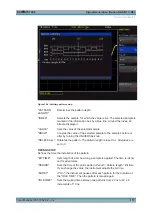
An information box is displayed for each bus, displaying the connector assignment.
Adjust the bitrate of the selected bus.
Pattern Generator


