background image

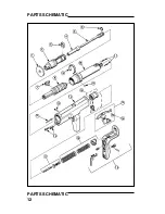
PARTS LISTING / MAINTENANCE

PARTS LISTING / MAINTENANCE

13

 COBRA TOOL PARTS LIST

KEY

PART NO.

DESCRIPTION

1

SC301500

SPALL GUARD

2

SC301009

FRONT BARREL (BASEPLATE )

3

SC301011A

SHEAR CLIP (PKG. OF 3)

4

SC301010

FASTENER GUIDE

5

SC301200A

PISTON ASSEMBLY

6

SC301208

PISTON RING

7

SC302012

PAWL ( STOP )

8

SC301006

REAR BARREL ( PISTON SLEEVE )

9

SC301014A

BARREL RETENTION ASSEMBLY

 10

SC301016

PUSH PIN

 11

SC301046A

DETENT BALL ASSEMBLY

 12

SC301034A

TRIGGER ASSEMBLY AND PIN

 13

SC301001

TOOL  BODY

 14

SC301113

BOLT ( 2 )

 15

SC301300A

SEAR HOLDER ASSEMBLY

 16

SC301531

SPRING, ADVANCE BAR

 17

SC301400

FIRING PIN ASSEMBLY

 18

SC301026A

FIRING PIN SPRING ASSEMBLY

 19

SC301600

HANDLE ASSEMBLY

MAINTENANCE

IMPROPERLY MAINTAINED TOOLS CAN CAUSE SEROIUS INJURIES

TO TOOL OPERATORS AND BYSTANDERS

CLEAN TOOL DAILY

Always  make sure the tool is not loaded before performing any service or
repair and always wear safety goggles when cleaning or servicing the tool.

NORMAL CLEANING

All front end parts shown in the disassembly section are to be cleaned daily with a
good detergent oil and wire brush. Remove all dirt and carbon buildup and wipe
parts dry with a clean rag. Check all parts for wear or damage before reassembly
and replace or repair any worn or damaged parts.

COMPLETE CLEANING / GENERAL MAINTENANCE

Heavy use or constant exposure to dirt and debris may require that the tool be
cleaned  more extensively. Complete disassembly and cleaning of all parts may be
necessary to restore the tool to normal operation. General maintenance should be
performed every six months or more often if the tool is subjected to heavy use.
Contact your authorized Ramset Distributor for assistance.

ALWAYS FUNCTION TEST THE TOOL AFTER PERFORMING ANY SERVICE.

SEE PAGE 9 FOR DETAILS ON THE FUNCTION TEST.

Summary of Contents for Cobra Tool

Page 1: ...BY LICENSED OPERATORS ONLY READ AND OBEY ALL SAFETY AND OPERATING INSTRUCTIONS BEFORE OPERATING TOOL COBRA TOOL OPERATOR S SAFETY OPERATING INSTRUCTION MANUAL SEMI AUTOMATIC LOW VELOCITY PISTON TYPE FASTENING TOOL DANGER ...

Page 2: ...oading end of the tool A serious hand injury from penetration by the piston or a discharged fastener could result DANGER Just as no one can merely read a book about driving an automobile and then hope to drive one safely no one should attempt to use any Ramset tool without adequate competent personal instruction And just as one must be licensed to drive an automobile one must also be licensed to u...

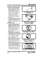
Page 3: ...er side endangering those in the path of the fastener Never fasten into any base material that does not pass the Center Punch test Failure to assure the suitability of the base material can result in serious injury to the eyes or other body parts NEVER FASTEN INTO VERY HARD OR BRITTLE MATERIALS NEVER FASTEN INTO SOFT MATERIALS SUCH AS DRYWALL Center Punch Test ALWAYS WEAR SAFETY GOGGLES WHEN PERFO...

Page 4: ...m flying debris and loss of hearing from constant or repeated unprotected exposure to fastening noise 2 Always keep the work area clear of bystanders and unnecessary materials that could interfere with safe tool operation Operating the tool in a congested or cluttered area may affect your ability to operate the tool safely 3 Never operate tool if flammable or explosive materials are nearby Powder ...

Page 5: ...d of the tool Serious hand injury could result from being struck by either a fastener or the tool piston should the tool be accidentally fired 6 Always store the tool unloaded and keep the tool and the loads securely locked in a tool box Keep keys away from children and unlicensed persons 7 Always keep the tool pointed away from yourself and others 8 Never carry a loaded tool around the work area ...

Page 6: ...ener close to an edge or to another fastener See page 8 for guidelines ALWAYS FOLLOW THE MISFIRE PROCEDURE If the tool does not fire after pull ing the trigger continue to hold the depressed tool against the work surface for at least 30 seconds Then carefully open the tool remove the load strip and put it in a can of water or other non flammable liquid Never carelessly discard a strip with live lo...

Page 7: ...s FASTENERS 145 Shank Diameter in Shank lengths from 1 2 to 2 1 2 145 Shank Diameter in Shank Lengths from 1 to 3 145 Shank Diameter in Shank Lengths of 1 2 and 1 and thread lengths of 1 2 3 4 and 1 150 Straight Shank in Shank Lengths from 1 2 to 7 8 150 180 Step Shank in Lengths from 1 to 1 7 8 145 Shank Diameter in Shank Lengths from 1 2 to 1 LOADS RS 27 10 SHOT STRIP LOAD POWER CATALOG LOAD CAS...

Page 8: ... The primary exception to the 3 edge distance can occur in a sill plate application where by necessity the edge distance is reduced Driving fasteners too close to an edge or too close to each other can cause the concrete edge to fail or fasteners to fly free Fastening to Concrete Block or to Masonry Walls While this application is not recom mended when used it is necessary to take care to observe ...

Page 9: ...re that the barrel is fully extended and then close the tool to the semi closed position This assures that the piston is in position for the next fastening Use the spall guard every time possible to minimize the risk of being struck by flying debris 2 With finger off the trigger place the fastener point out into the muzzle end of the tool until the point end is inside the muzzle NEVER load a faste...

Page 10: ...d into place for the next fastening 7 Insert another fastener in the muzzle end of the tool as before and the tool is ready for the next fastening Keep your finger off of the trigger until the tool is in position to drive the fastener 8 To remove a used or partially used load strip from the tool pull the strip out from the top of the tool Do not try to remove the strip by pulling it out from the b...

Page 11: ...embly Reduction or loss of Piston not being returned Barrel must be pulled power to the full rear position completely open to properly position the piston Worn or damaged piston Replace worn or or piston ring damaged parts Worn or broken pawl Replace pawl Tool cannot be cocked or Excessive dirt buildup Clean tool thoroughly opened Damaged or bent piston Replace piston Broken or damaged parts Tag t...

Page 12: ...PARTS SCHEMATIC PARTS SCHEMATIC 12 15 13 12 10 12 16 11 14 18 17 19 ...

Page 13: ...AILY Always make sure the tool is not loaded before performing any service or repair and always wear safety goggles when cleaning or servicing the tool NORMAL CLEANING All front end parts shown in the disassembly section are to be cleaned daily with a good detergent oil and wire brush Remove all dirt and carbon buildup and wipe parts dry with a clean rag Check all parts for wear or damage before r...

Page 14: ... 4 Unseat and remove the shear clip by prying it up with a flat blade screwdriver or fastener point Remove the clip from the barrel by prying it up and away from the groove in the barrel Use care to keep the clip from flying free when it is removed 5 Separate the front barrel and guide from the rear barrel assembly ROTATE THE BARREL RETEN TION CLIP AWAY FROM PAWL REMOVE THE PAWL REMOVE THE BARREL ...

Page 15: ...ll length of the piston must not be less than 5 5 8 long When less than 5 5 8 long the piston must be replaced to avoid tool damage 8 Reassemble the tool in the reverse order of disassembly When sliding the front barrel onto the rear barrel align the groove in the rear barrel with the groove in the front barrel 9 Align the groove in the rear barrel with the pawl opening in the tool body when placi...

Page 16: ... THIS IS THE SOLE WARRANTY OF RAMSET AND THE SOLE REMEDY AVAILABLE TO THE BUYER AND IN NO EVENT WILL ANY DIRECT OR INDIRECT INCIDENTAL OR CONSEQUENTIAL DAMAGES OR ANY OTHER DAMAGES BE AVAILABLE Copyright 2000 ITW Ramset Red Head THE COBRA TOOLCOMPLIES WITH OSHA REQUIREMENTS AND WITH ANSI A10 3 SPECIFICATIONS FOR TOOL REPAIR SERVICE CONTACT YOUR LOCAL AUTHORIZED ITW RAMSET RED HEAD DISTRIBUTOR OR C...

Reviews: