INSTALLATION AND OPERATING INSTRUCTIONS
High Flow Water Filter Models BH010 & BH020
(Please read thoroughly BEFORE proceeding. Please save for future reference.)
INTRODUCTION
These units are for use in situations requiring flow rates up to 20gpm/75L/min (Model BH010 -13 3/4” Height) and 40gpm/151L/min (Model BH020 - 23
5/8” Height) These High Flow Water Filter Housings help protect plumbing fixtures, water heaters and appliances.
Unique double o-ring design provides an extra water tight seal.
Cartridge not included.
For dirt, rust, algae filtration use Rainfresh cartridges BC101, BC1 or BC3 in the BH010 and BC201, BC205 or BC225 in the BH020.
For taste/odour, chlorine and sediment reduction use BC2 in the BH010 and BC202 in the BH020 (Note: Rated flow for BC2 and BC202 is 3 US GPM and
6 US GPM only)
These units have 1” Female NPT Inlet and Outlet Threads.
Wrench included and Mounting Bracket sold separately
I
NSTALLATION PRECAUTIONS & OPERATING SPECIFICATIONS & GUIDELINES
For use on main cold water line only.
Always install after your pump and pressure tank or on city water after your meter and your main shut off valve.
Caution:
The rubber O-rings provide a water tight seal between the head and sump. It is important that they are properly
seated in the grooves
of
the sump or a water leak could occur.
Use only with municipally treated or microbiologically safe water. The cartridges above
Do Not
remove harmful bacteria. For effective disinfection
install a Rainfresh DS3, UCSSM, UCS2, DS2, SST, FC000/1M or CT1M Drinking Water System or a R519, R830 or R1245 UV Water Disinfection system.
- Do Not
install in direct sunlight
Max Operating Temperature
: 100o F / 38o C.
Prevent unit from freezing
Maximum operating pressure:
100 psi / 6.9 bar. If you suspect that your water pressure will at any time exceed the rated pressure, a pressure
regulator
must be installed
before the filter housing. This will guard against the water pressure exceeding the maximum pressure rating. It is
recommended that the pressure regulator be set at 75 psi / 5.2 bar or less.
ELECTRICAL GROUNDING:
If water pipes are used to ground your electrical system, install jumper wire across the filter unit.
INSTRUCTIONS FOR INSTALLATION
Instructions are for installing the BH010 housing on to 3/4” copper pipe
using copper or brass solder fittings. If the unit is to be installed on any
other type of pipe (plastic, PVC, Pex or Iron pipe) different hardware must
be purchased. Consult a qualified plumber or call Rainfresh for help.
Tools Required
Adjustable wrench, pipe cutter, file or sand cloth, thread seal tape,
soldering torch, flux & lead-free solder, pencil or marker
Fittings Required
- 1”NPT male adapters (2) and 1”x3/4” reducers (2), 3/4” unions (2). It is
recommended that you build a by-pass around the unit so that in case
filter needs to be removed for service, unfiltered water can still be used in
the house. To build the by-pass, you will need 3/4” copper tees (2), 3/4”
elbows (2) and 3/4” ball valves (3).
- The filter should only be installed vertically as shown. The inlet/outlet
ports can be on either side.
- Optional mounting bracket is sold separately (necessary for installation
on PVC, plastic or PEX pipe).
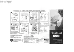
Recommended Installation Procedure
Locate the best position for the water filter where there is easy access for
filter cartridge changes. This housing should be installed on the main
water line right after the water meter or pressure tank. Allow at least
three (3) inches above and below filter for clearance. Some water spillage
may occur during
filter cartridge changes. Therefore installing near a floor drain is
preferable.
a)
Solder the 1”x 3/4” reducer on to the 1” male adapters and solder at
least 2” pipe length to it. Solder one end of the union to the other end of
the 2” pipe and allow to cool to room temp. Repeat for other side. Do not
thread in adapters before soldering the reducers as soldering near the ports
can cause damage to the unit and may cause a leak.
pg 1.
Fig A
b)
Apply 4 to 5 wraps of thread seal tape, in a clockwise direction to the male threads of each adapter.
DO NOT
use pipe joint compound, wicking or
sealer on any parts connecting to filter housing.
c)
Remove the sump from the filter heads and put aside until later. Using an appropriate sized adjustable wrench, screw in the adapters to the inlet and
outlet ports of the housing, taking care not to cross-thread.
DO NOT OVERTIGHTEN
fittings into plastic filter head or it may crack, about one to two
thread(s) should remain visible.
d)
Turn off water supply now and open a nearby faucet to drain water out of pipes and relieve pressure. Once all the water from the pipes is
drained,measure and cut pipe as required and plumb in other fittings as shown in either fig A.
CAUTION:
To protect the housing from damage due to
heat from soldering, wrap the ports in a wet cloth during soldering.