8
Installation Instructions
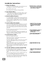
1. Safety Precautions
• To prevent an accident and/or injury, do not hoist the unit over
your shoulder. Use a hand truck to transport the unit.
• Do not lay the unit on its side.
• Wear safety glasses and work gloves during installation.
2. Test the Raw Water
• If water contains iron, manganese or hydrogen sulfide, a seperate
iron removal system is suggested to be installed prior to the
conditioner. Please consult with your local dealer.
3. Check the Water Pressure
• Use a pressure gauge to confirm that the water pressure does not
exceed 100 psi. If the water pressure does exceed this limit, install
a pressure regulator on the inlet pipe of the unit. The minimum
water pressure for a conditioner is 20 psi. 60 psi is the optimum
operating pressure.
4. Locate a Site for the System
• There are three primary requirements needed for a site: the main
water source, an air-gap drain and a grounded electrical connec-
tion. Locate the system as close to these items as practical. Drain
lines over 50 feet long, may need to be increased in size to allow the
proper flow.
• Place the system in the desired location. The location should have
a level, smooth, and clean surface.
• If the system is located outdoors, protect the unit from direct sun-
light. Direct sunlight can damage the fiberglass and other system
components. If necessary, build a box or shed.
5. Install the Valve Head
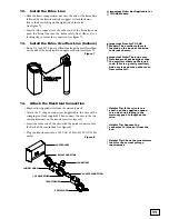
• Remove the cap plug from the tank.
• Lubricate the riser pipe O-ring and tank O-ring with Dow 111
silicone-based lubricant or equivalent.
• Attach the supplied upper basket to the bottom of the control
valve; twist to lock in place. Do not use if water contains any
amount of iron.
• Align the upper basket with the riser pipe and slowly lower the
control valve onto the riser pipe, using a twisting motion.
• Align the control valve with the tank. Push down on the control
valve and continue to turn it clockwise until the valve o-ring seals
against the tank.
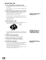
6. Turn Off the Water and Drain the Plumbing
• Turn off the water at the meter or the pressure tank.
• To drain the plumbing system, open all faucets in the house and
flush the toilets. The water will drain out of the lowest faucet or
outlet.
• Do not sweat pipes with water in them or while attached to the
system; steam will damage the plastic parts in the valve.
• Do not point the soldering torch directly at the mineral tank or
control valve. These composite materials will last a lifetime, but
cannot withstand the intense heat from a torch.
Helpful Tip: The drain may be a
floor drain, a sewer trap, utility
sink, vent stack, dry well, etc.,
depending on local plumbing
codes.
Important Note: The system can
only be installed outdoors in
climates that do not reach
freezing levels.
Important Note: Do not over-
tighten the valve to the tank.
Helpful Tip: This procedure will
allow air to enter the plumbing
system.
Important Note: Not Applicable
for TC-CAB and SS Models.
Important Note: Applicable for
copper plumbing installations.
Important Note: For Massachusetts
Residents Only: The Commonwealth of
Massachusetts Plumbing Code 248 CMR
shall be adhered to. A licensed plumber
shall be used for this installation.
Summary of Contents for TC 100 CV
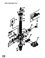
Page 18: ...18 18 Valve Exploded View ...
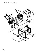
Page 20: ...20 Control Exploded View 20 ...
Page 23: ...23 Notes ...
Page 44: ...44 Vista despiezada de la válvula ...
Page 46: ...46 Vista despiezada del control ...
Page 49: ...49 Notas ...
Page 50: ...50 Notas ...
Page 51: ...51 Notas ...

