4
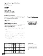
Operational Specifications
Plumbing
3/4 inch to 1 1/4 inch I.D.
Drain Line
1/2 inch I.D.
Water Pressure
20 psi_120 psi (1.38 bar _ 6.89 bar)
Operating Temperatures
40° F_100° F (4.4° C _ 37.8° C)
Electrical Requirements
A properly grounded alternating current supply (110 VAC 60 Hz or 230
VAC 50 Hz) is required for the operation of this system. Please check the
transformer for the correct voltage requirements.
Bypass Valve
The bypass valve enables you to bypass the system in situations of: emer-
gency leaks in the equipment, service calls.
Existing Plumbing Conditions
Plumbing should be free from lime and/or iron buildup. Piping that
contains large amounts of lime and/or iron should be replaced.
Additional Specifications
• Do not install this system where water is microbiologically unsafe or of
unknown quality without adequate disinfection before or after the
system.
• This system must be installed in accordance with all applicable state
and local laws and regulations.
• The Commonwealth of Massachusetts Plumbing Code 248 CMR shall
be adhered to. A licensed plumber shall be used for this installation.
• This system must be installed in an area not affected by extreme heat,
cold or the elements. The selected installation area must be adequate
for easy service and accessibility.
• This system is designed to treat cold water only. The installation must
be on a cold water supply.
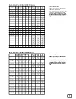
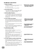
Data Chart for ION-X 2000 V Resin
*
Cation Exchange Media
Higher or lower pressure will affect the
efficiency of the system.
If the iron content of the water to be soft-
ened is zero, and the hardness level is
less than 20 gpg, we suggest you choose
the low salt setting for the most efficient
operation. Please go to page 13 for the
instruction of how to set the pounds of
salt.
Important Note: This system
requires the use of the supplied
transformer (24 VAC).
Model
Tank Size
(inches)
Resin*
(cu. ft.)
Service
Flow
(gpm)
Drain
Flow
(gpm)
psi Drop
High
Salting
Medium
Salting
Low
Salting
TC 50 V
8 x 44
0.5
10
1.5
14.0
17,400 @
7.5 lbs.
14,200 @
5.0 lbs.
6,600 @
1.5 lbs.
TC 50 CV
8 x 44
0.5
10
1.5
13.0
17,400 @
7.5 lbs.
14,200 @
5.0 lbs
6,600 @
1.5 lbs.
TC 60SS V
10 x 18
0.6
9.5
2.0
9.0
19,000 @
9.0 lbs.
15,500 @
6.0 lbs.
7,200 @
1.8 lbs.
TC 60SS CV
10 x 18
0.6
9.5
2.0
8.0
19,000 @
9.0 lbs.
15,500 @
6.0 lbs.
7,200 @
1.8 lbs.
TC 60S V
10 x 35
0.6
9.5
2.0
9.0
19,000 @
9.0 lbs.
15,500 @
6.0 lbs.
7,200 @
1.8 lbs.
TC 60S CV
10 x 35
0.6
9.5
2.0
8.0
19,000 @
9.0 lbs.
15,500 @
6.0 lbs.
7,200 @
1.8 lbs.
Important Note: The manually
operated bypass valve enables
the conditioner to be isolated
from the water service line for
maintenance and service. It
also maintains the continuity of
the water supply when the
conditioner is disconnected.
Summary of Contents for TC 100 CV
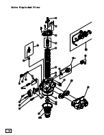
Page 18: ...18 18 Valve Exploded View ...
Page 20: ...20 Control Exploded View 20 ...
Page 23: ...23 Notes ...
Page 44: ...44 Vista despiezada de la válvula ...
Page 46: ...46 Vista despiezada del control ...
Page 49: ...49 Notas ...
Page 50: ...50 Notas ...
Page 51: ...51 Notas ...

