background image

78

Integrated Sensor System

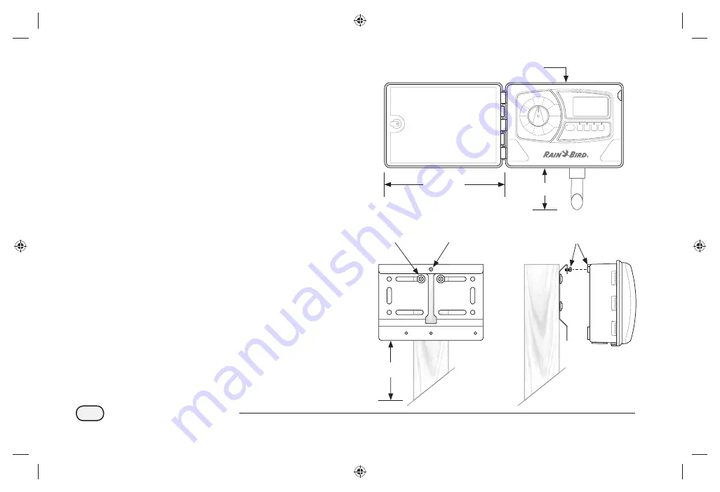
Data Logger and Repeater Installation

To Install the Data Logger or Repeater:

Determine the exact location of the Data Logger or 
Repeater based on the site survey. Each unit must be 
installed on a fl at, stable surface such as a 4x4 wooden post 
or a metal stake (U-bolt would be required).

NOTE: 

Allow at least 12” of horizontal clearance to the 

left side of the unit, to allow the hinged door to swing 
fully open. For ISDL-2400 Data Loggers, leave at least 
3” of clearance under the unit for cable conduit.

The unit must be mounted at least 5 ft. above grade to 
ensure wireless network communication.


Attach the mounting bracket, using appropriate 
hardware for the location surface.

Insert one of the four provided machine screws into 
the top hole of the mounting bracket, and tighten 
until a 1/8” gap remains.

Hang the ISDL-2400 or ISR-2400 on the screw using 
the keyhole slot located on the back of the unit. Make 
sure the screw is secure in the narrow part of the 
keyhole slot.

RADIO

BASIC

Auto

Manual

SPECIAL

FEATURES

SYSTEM

RESET

SENSOR

SETUP

CONFIGURE

DATA

LOGGER

SD

CARD

INFO

SENSOR

SENSOR

OFF

BACK-LIGHT

ISDL-2400

Wireless Data Logger

12in +

3in +

5ft

Facing
View

Side
View

Keyhole 
Slot

Machine 
Screw

(ISDL Shown)

Summary of Contents for ISDL-2400

Page 1: ...Integrated Sensor SystemTM ISS Installation Programming Operation Guide...

Page 2: ...communications However there is no guarantee that interference will not occur in a particular installation If the equipment does cause harmful interference to radio or television reception which can b...

Page 3: ...enna 6 Soil ManagerTM Software 6 Programming the ISDL 2400 Data Logger 7 Programming Overview 7 Auto Sensor 8 Sensor Addresses 8 Sensor Types 8 Soil Data 8 Last Reading 8 Next Reading 8 Auto Basic 9 C...

Page 4: ...ensor Reading 24 Manual Radio 26 Radio Status 26 Last Wake 26 Next Wake 26 Last SYNC 26 Link Status 26 Manual Radio Wake 27 System Reset 28 Reset 28 Factory Defaults 28 Reset 28 Factory Defaults 29 SD...

Page 5: ...Date Format 40 Hour Format 40 Select Language 41 Set Date Time 42 Select Date Format 44 Select Hour Format 45 Upgrade Firmware 46 Manual Radio 48 Radio Status 48 Last Wake 48 Next Wake 48 Last SYNC 48...

Page 6: ...Installation Tools Required 70 Sensor Installation Overview 72 Sensors 72 Wire Paths 72 Valve Boxes 72 Sensor Installation 74 Wire Path Installation 75 Valve Box Installation 76 Data Logger and Repea...

Page 7: ...analyzes data to determine optimum watering requirements that match specific target conditions across the site Battery powered system components allow ultimate flexibility for soil monitoring data co...

Page 8: ...real time soil data moisture temperature and salinity levels at various locations on the irrigation site Wireless Data Loggers record and transmit soil data over a Wireless Mesh Network Wireless Repea...

Page 9: ...oil conditions The sensors do not require calibration and provide accurate readings immediately after installation Sensors connect to an ISDL 2400 Data Logger using a three conductor AWG 18 gauge irri...

Page 10: ...intervals or can operate in a stand alone mode to provide instant real time soil readings from the sensors Each ISDL 2400 supports up to 18 soil sensors on two channels nine sensors per channel Contro...

Page 11: ...rk The ISS supports a maximum of 40 Wireless Repeaters over the entire network A maximum of 7 hops allowed from end node to Wireless ISG 2400 Gateway router Unobstructed line of sight range is at leas...

Page 12: ...esh network and the Central Control Software The Gateway communicates with the network of ISDL 2400 Data Loggers and ISR 2400 Repeaters through a roof mounted radio antenna and routes data to and from...

Page 13: ...tage and wireless link quality are sent to the Central Control Software Soil Manager at regular intervals When the dial is in any other switch position radio communication with the network continues b...

Page 14: ...for each sensor Last Reading The elapsed time since the last sensor reading is displayed Next Reading The time remaining until the next sensor reading is displayed Turn the dial to Auto SENSOR The Aut...

Page 15: ...MED or HIGH Last Sync The elapsed time since the last Soil Managernetwork update is displayed Radio Status The current status of the radio is displayed as Awake Sleep or Setup NOTE Details on Radio Mo...

Page 16: ...d time can be re entered manually but it is recommended to let the Soil Managerupdate the values automatically during the next network sync Date Format Three different date formats are available MM DD...

Page 17: ...BASIC Sample Rate The sample rate determines how often the ISDL 2400 records soil data from the sensors When the radio is on the sample rate of 2 120 minutes is controlled by the Soil Manager If commu...

Page 18: ...cted Press the or buttons to set the current year then press NEXT Hour is selected Press the or buttons to set the current hour then press NEXT Set Date Time Used to manually enter system date and tim...

Page 19: ...ure screen appears Press the UP or DOWN button to select Date Format then press OK The Date Format screen appears Press the UP or DOWN button to select the desired date format then press OK When nishe...

Page 20: ...ect Hour Format then press OK The Hour Format screen appears Press the UP or DOWN button to select 24 Hour or 12 Hour then press OK When nished turn the dial to Auto SENSOR or BASIC Select Temperature...

Page 21: ...sensors measure soil conditions NOTE The sample rate will need to be manually set if the radio is off or network communication is lost Turn the dial to CONFIGURE DATA LOGGER The Configure screen appea...

Page 22: ...K The Update Firmware screen appears The Confirm firmware update message is displayed Press the 2 and 4 buttons together for 3 seconds to initiate the update The Update Firmware message displays Check...

Page 23: ...creen NOTE An alternate procedure to upgrade the firmware is to turn off the power switch inside the ISDL turn the dial to Configure Data Logger insert the SD card with the new firmware file and turn...

Page 24: ...rer is 0 Remove Sensor The ISDL 2400 removes the address of a selected sensor from the Data Logger database and the removed address is made available to new sensors Query Channel Sensor Address This f...

Page 25: ...Sensor Setup screen appears Press the UP or DOWN button to select Add Ch 1 or Ch 2 then press OK The Add Sensor screen appears Press the UP or DOWN button to select an available slot then press OK The...

Page 26: ...When nished turn the dial to Auto SENSOR or BASIC Remove Sensor The ISDL 2400 removes the address of a selected sensor from the Data Logger database and the removed address is made available to new se...

Page 27: ...n can be pressed to change the sensor address back to 0 This should always be pressed when installing a new sensor on the ISDL to verify the address is 0 When nished turn the dial to Auto SENSOR or BA...

Page 28: ...e Sensor Setup screen appears Press the UP or DOWN button to select Scan Sensors then press OK The Sensor Scan screen appears and begins scanning When complete the number of installed sensors and the...

Page 29: ...this page intentionally left blank...

Page 30: ...can be found in the Appendix section page 89 Soil Data Last measured moisture temperature and salinity levels are displayed for each sensor Last Reading The elapsed time since the last sensor reading...

Page 31: ...00 09 35 00 05 25 READ Sensor 2 Type 3 63 8 F 18 3 M 0 21 dS The screen shows Reading while taking new soil measurements Manual Sensor Last Next 00 09 35 00 05 25 Reading 2 READ Sensor 2 Type 3 63 8 F...

Page 32: ...p to Awake is displayed Next Wake The time remaining until the next scheduled Wake is displayed Last SYNC The elapsed time since the last sync command from the Soil Manager is displayed Link Status Th...

Page 33: ...Turn the dial to MANUAL RADIO The Manual Radio screen appears If the Radio Status is SLEEP press the WAKE button to change the status of the radio to Awake NOTE Radio will wake for approximately 20 3...

Page 34: ...o default factory values NOTE After the Factory Default function is performed all sensors are un installed from the data logger Each connected sensor keeps its last assigned address but no sensors ins...

Page 35: ...BASIC Factory Defaults This function resets all system settings except date and time to default factory values Turn the dial to SYSTEM RESET The System Reset screen appears Press the UP or DOWN butto...

Page 36: ...dy is displayed Card Capacity The capacity of the installed SD card is displayed in MB megabytes Card Free Space The amount of available space on the installed SD card is displayed in MB megabytes NOT...

Page 37: ...factory default address is 0 Features ISDL Version 1 0 Radio Version 804B Node 13A200 403B6CE2 Host 13A200 4033F656 DIAGNOSTIC Diagnostic Tests The following diagnostic tests are available Diagnostic...

Page 38: ...nished turn the dial to Auto SENSOR or BASIC The Enter Password message is displayed Enter 4132 If the correct password is not entered after 10 seconds Invalid password or timeout is displayed Press R...

Page 39: ...rsion 1 0 Radio Version 804B Node 13A200 403B6CE2 Host 13A200 4033F656 DIAGNOSTIC The Enter Password message is displayed Enter 4132 If the correct password is not entered after 10 seconds Invalid pas...

Page 40: ...creen appears Press M TEST key to start manufacturing functional test is displayed Press M TEST Run Diagnostic Test 3 Performs a manufacturing functional test that displays the status of various ISDL...

Page 41: ...nsor System Testing message is displayed while conducting the test When complete the MFG TEST RESULTS screen appears Press RETRY to conduct the test again if desired When nished turn the dial to Auto...

Page 42: ...Integrated Sensor System O Position This position sets the ISDL 2400 into low power mode and keeps the internal clock and microprocessor running Sensor readings and radio communications are terminate...

Page 43: ...ally The LCD on the front panel provides access to a variety of programming functions such as setting date and time or upgrading firmware NOTE If the ISR 2400 is not powered on open the front panel Se...

Page 44: ...radio prepares to listen to network commands Home 09 23 2010 03 28 45 Vbat HIGH Link HIGH Last SYNC Radio Status Awake 01 39 35 MENU WAKE Home Screen The Home screen displays basic system information...

Page 45: ...o status view SD card information conduct range tests or perform diagnostic tests Home Press HOME to return to the Home screen Programming Buttons Use the UP DOWN and OK buttons to make programming se...

Page 46: ...settings or sensor configuration Con guration This option provides the capability to manually change system settings Language Eight different languages are available English Italian Spanish Portuguese...

Page 47: ...ress the UP or DOWN button to select Language then press OK The Select Language screen appears Press the UP or DOWN button to select the desired language then press OK Select Language Seven different...

Page 48: ...n appears with the month selected Press the or button to set the current month then press NEXT Day is selected Press the or button to set the current day then press NEXT Set Date Time Used to manually...

Page 49: ...ute is selected Press the or button to set the current minute then press DONE Year is selected Press the or button to set the current year then press NEXT Hour is selected Press the or button to set t...

Page 50: ...23 2010 03 28 45 Vbat HIGH Link HIGH Last SYNC Radio Status Awake 01 39 35 MENU WAKE The Menu screen appears Press the UP or DOWN button to select Configuration then press OK The Configure screen app...

Page 51: ...010 03 28 45 Vbat HIGH Link HIGH Last SYNC 01 39 35 Radio Status Awake MENU WAKE The Menu screen appears Press the UP or DOWN button to select Configuration then press OK The Configure screen appears...

Page 52: ...U button Home 09 23 2010 03 28 45 Vbat HIGH Link HIGH Last SYNC Radio Status Awake 01 39 35 MENU WAKE The Menu screen appears Press the UP or DOWN button to select Configuration then press OK The Conf...

Page 53: ...ER OFF Updating firmware NOTE Do not turn off power to the ISR 2400 when updating firmware When completed the Rain Bird splash screen is briefly displayed before a return to the Update Firmware screen...

Page 54: ...Wake The time remaining until the next scheduled Wake is displayed Last SYNC The elapsed time since the last Soil Managerupdate is displayed ON OFF Toggles between ON and OFF depending on the power st...

Page 55: ...o screen appears Manual Radio Status Last Wake Next Wake Last SYNC HOME OFF WAKE Awake 00 00 41 00 00 53 01 39 35 NOTE If required press OFF or ON to cycle power to the radio Press WAKE to change the...

Page 56: ...button to select System Reset then press OK The System Reset screen appears Press the UP or DOWN button to select Reset then press OK System Reset This option performs a system reset or returns syste...

Page 57: ...51 Integrated Sensor System When completed the Rain Bird splash screen is briefly displayed before a return to the Home screen Rain Bird ISR 2400 Repeater...

Page 58: ...s the MENU button Home 09 23 2010 03 28 45 Vbat HIGH Link Last SYNC Radio Status Awake 01 39 35 MENU WAKE The Menu screen appears Press the UP or DOWN button to select System Reset then press OK The S...

Page 59: ...t be accurately displayed if the SD card has been used in other digital media such as a digital camera or music player An SD card reader and personal computer can be used to check the free space Check...

Page 60: ...ures are found on pages 66 69 in the Installation section of this manual NOTE Do not conduct range tests when the mesh network is operating This feature is intended for installation or troubleshooting...

Page 61: ...default address is 0 Features ISR Version 1 0 Radio Version 804B Node 13A200 403B6CE2 Host 000000 00000000 DIAGNOSTIC BACK HOME Diagnostic Tests The following diagnostic tests are available Diagnosti...

Page 62: ...e Menu screen appears Press the UP or DOWN button to select Special Features then press OK The Features screen appears Press and hold the second and third buttons until the Diagnostic screen appears F...

Page 63: ...stem The Diagnostic 1 screen and test results are displayed Diagnostic 1 EXIT WAKE Radio Status RSSI Battery Packet Awake 78 dBm 4 89 0 0 MED HIGH NOTE If necessary press WAKE to change the radio stat...

Page 64: ...Awake 01 39 35 MENU WAKE The Menu screen appears Press the UP or DOWN button to select Special Features then press OK The Features screen appears Press and hold the second and third buttons until the...

Page 65: ...reen appears press the button Diagnostic 1 EXIT WAKE Radio Status RSSI Battery Packet Awake 78 dBm 4 89 0 0 MED HIGH The Diagnostic 2 screen and test results are displayed NOTE If necessary press WAKE...

Page 66: ...he Features screen appears Press and hold the second and third buttons until the Diagnostic screen appears Features ISR Version 1 0 Radio Version 804B Node 13A200 403B6CE2 Host 13A200 4033F656 DIAGNOS...

Page 67: ...tus RSSI Battery Packet Awake 78 dBm 4 89 0 0 MED HIGH The Diagnostic 3 screen appears Press M TEST key to Start manufacturing functional test is displayed Press M TEST Testing is displayed while cond...

Page 68: ...this page intentionally left blank...

Page 69: ...lling the ISS for the first time it is recommended that the Installation Checklist be used as a step by step guide to the installation process For your convenience a check off box is provided for each...

Page 70: ...east two other Repeaters to establish an alternate signal path Each Repeater should be installed within range of at least two other Repeaters The Gateway antenna should be within range of at least two...

Page 71: ...le Maintenance Building Antenna Data Logger Repeater DL R GA DL R GA R R R R DL DL DL DL DL DL DL DL R Key R R NOTE Each data logger must be in direct range of at least two repeaters or one repeater a...

Page 72: ...2400 ISR 2400 pair Verify at least two ISR 2400 s are within range of the base radio antenna Use the Site Survey map and the GPS locator to pinpoint proposed unit locations The locations can be adjust...

Page 73: ...wake MENU WAKE The Menu screen appears Press the UP or DOWN button to select Range Test press OK The Range Test screen appears Press the UP or DOWN button to highlight Transmit Mode do not press OK Ea...

Page 74: ...ode Radio Status RSSI 71 dBm Rx Tx 18 BACK CLEAR HOME The following screen is now displayed on ISR 1 Range Test Awake High 18 Loopback Mode Radio Status RSSI 72 dBm Packet count BACK CLEAR HOME Observ...

Page 75: ...Values RSSI Value dBm Relative Strength 92 to 85 Low 85 to 80 Medium Above 80 High Table 4 Packet Ratio RX TX Value Acceptable 90 100 Yes 0 90 No NOTE The RX TX value is displayed on the LCD as a rat...

Page 76: ...or any cable pulling equipment Sod cutter with mole kit vibratory plough etc 6 Three conductor AWG 18 gauge irrigation cable 7 Rain Bird DB series Wire Connectors 8 Valve Boxes 6 Required tools and m...

Page 77: ...71 Integrated Sensor System Figure 7 Installation Tools 1 11 12 9 8 7 6 5 4 3 2 10 13 14 15 16...

Page 78: ...the root zone and a lower sensor to monitor salinity conditions NOTE Sensors must be addressed before installation Prior to burial connect each sensor one at a time to the data logger and take a readi...

Page 79: ...DL 2400 Wireless Data Logger RADIO BASIC Auto Manual SPECIAL FEATURES SYSTEM RESET SENSOR SETUP CONFIGURE DATA LOGGER SD CARD INFO SENSOR SENSOR OFF ISDL 2400 Ch 1 Wire Path Valve Box Sensor Cable Sen...

Page 80: ...should be placed deep enough to avoid damage from deep tine aerification Set sensor s into the bottom of the hole and run each sensor cable into the trench and back to valve box location Push one sen...

Page 81: ...with blade mole kit or a vibratory plough lay cable around the green deep enough to avoid damage from aerification as shown in Figure 14 Start at either the data logger or the furthest valve box loca...

Page 82: ...g a wire stripper and Rain Bird DB series wire connectors connect the sensor cable to the wire path as shown Table 5 Cable Wires Cable Data Power Ground Wire Path Green Red White TSM 3 Type 3 Blue Red...

Page 83: ...400 or ISR 2400 and are required for installation If anything is missing please contact your distributor before proceeding 1 ISDL 2400 or ISR 2400 unit 2 Ribbon Cable 3 Antenna 4 Antenna Rubber O Ring...

Page 84: ...le conduit The unit must be mounted at least 5 ft above grade to ensure wireless network communication Attach the mounting bracket using appropriate hardware for the location surface Insert one of the...

Page 85: ...it makes installation easier the front door and front panel can be removed and then re attached when installation is complete Insert the remaining three machine screws through the mounting holes on th...

Page 86: ...he rubber o ring provided over the brass terminal post on top of the unit then screw the antenna securely to the post The connection should be tight For ISR 2400 Repeater set the internal ON OFF switc...

Page 87: ...oute wire paths through the conduit and up through the knock out hole in the bottom of the ISDL 2400 unit Connect the wires to the Ch 1 or Ch 2 posts and label each wire clearly for future reference S...

Page 88: ...m wireless network reception This can be on the roof the building where the central workstation is located or else another appropriate location To Install the Antenna Install the antenna according to...

Page 89: ...tenna Connector jack on the ISG 2400 Gateway Connect the USB cable to the Gateway and an open USB port on the workstation computer preferably on the back of the computer to prevent accidental removal...

Page 90: ...this page intentionally left blank...

Page 91: ...iod interval and the length of time that the radio mode changes to Awake is controlled at the central workstation by a sync command from the Soil Manager Several programming features of the ISDL 2400...

Page 92: ...ies The battery levels are displayed at each unit Vbat and sent to the central workstation Estimated minimum battery life is twelve months in 20 C 68 F environment assuming 100 readings per day To rep...

Page 93: ...unlock the door of the unit with the supplied key Then open the door of the unit and swing it to the left Open the front panel and swing it open to the left exposing the interior of the unit To remove...

Page 94: ...se while operating or installing the ISSTM General Troubleshooting Table 7 General Troubleshooting Problem Solution No display on LCD Press backlight button If display doesn t light up check batteries...

Page 95: ...Step 5 if the error does not clear Step Action 5 Check the wiring connections to the terminals inside the ISDL 2400 a Inspect wires for open and or short circuits b Verify wires are connected to the c...

Page 96: ...Value Details Radio Status Awake or Sleep Shows current radio status Last Wake hr min sec Elapsed time since last wake Next Wake hr min sec Time until next wake Last SYNC hr min sec Elapsed time sinc...

Page 97: ...Figure 9 Type 3 Sensor Installation 74 Figure 10 Wire Path Installation 75 Figure 11 Valve Box Wiring Diagram 76 Figure 12 Box Contents 77 Figure 13 Antenna Installation 82 Figure 14 ISG 2400 Gateway...

Page 98: ...this page intentionally left blank...

Page 99: ...1000 4 2 EN61000 4 3 Model Numbers Data Logger ISDL 2400 EN61000 4 4 Repeater ISR 2400 EN61000 4 6 Soil Sensors TSM 1 TSM 3 ETSI EN 301 489 1 ETSI EN 301 489 17 I the undersigned hereby declare that t...

Page 100: ...opyright 2011 by Rain Bird Corporation All rights reserved This material may not be published or reproduced without permission Rain Bird Integrated Sensor System and Soil Manager are registered tradem...

Reviews: