background image

14

INDOOR CONTROLLER (230 VOLT 50HZ IN-
TERNATIONAL VERSION)

Because of the wide variety of plug patterns used
for electrical wall outlets around the world, the in-
door controller provides a separate transformer with
a two-wire, 230 VAC input to which you can attach
the proper plug. After attaching the plug to the input
wires, do not plug the transformer in.

The transformer has plastic loops that allow you to
screw it to the wall surface at a convenient location.
The two 24 VAC output wires are to be attached to
the "24 VAC" screws before plugging in the power
cord. (See illustration.)

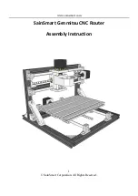
CONNECT FIELD WIRES TO REMOTE CONTROL VALVES

NOTE: The E-Class, residential controller is designed to work best with #18 gauge, multi-conductor cable that
is approved for low-voltage, direct burial applications. These cables usually have a white insulated wire for
Valve Common and then a different color wire for each station valve, all contained within an outer jacket.

The wires coming back to the controller from the electric valves in the field can be routed into the controller
through the larger hole(s) in the bottom of its cabinet. For a clean, professional look to the installation, the hole
size is for a 3/4" PVC conduit to house the wires (or for 1" PVC). The upper ends of the conduit(s) should end
about 1/4 inch inside the bottom of the controller.

If using a pump: connect unused stations to the closest used ones.

SENSOR

SYSTEM

MASTER

VALVE

STATION VALVES

Summary of Contents for E-3

Page 1: ...Please read the in structions carefully and keep this manual in a handy location for future reference PROGRAMMING CONTROLS The following is a key to the buttons and icons on the E Class controller fa...

Page 2: ...ll struggling with your old sprinkler timer Having a hard time complying with local watering restrictions Upgrading to a new Rain Bird sprinkler timer is easier than you might think New timers are eas...

Page 3: ...6 will flash in the display Press or to set to the current year 3 Press ENTER ENTER to enter your selection 4 The digits for the current month will now flash 01 Press or to set to the current month 5...

Page 4: ...s with today s number and abbreviation The seven weekdays are dis played as a row of numbers For example Mon day is 1 Tuesday is 2 etc 1 2 The square around a day s number means it is a water day To t...

Page 5: ...ress ENTER until the start time you want to delete appears in the display 4 Move the start time to the blank screen just before midnight The E Class controller automatically arranges start times in th...

Page 6: ...pears A B or C and then start over with STEP II VI ADJUST WATER BUDGET PERCENTAGE 1 WATER BUDGET allows you to increase or decrease watering time length for all stations on a Pro gram with just one ad...

Page 7: ...of minutes you want Normal station running times in the Automatic Programs are not affected 2 STATION 2 4 STOP AT ANY STATION YOU WANT use or to set a running time for it Use ENTER ENTER to put the s...

Page 8: ...the first stacked Program will blink 4 IX TO RUN THE TEST PROGRAM 1 2 3 You can manually advance through the stations of any program by setting the dial to AUTO and repeatedly pressing the ENTER ENTE...

Page 9: ...ean method use this dial posi tion and the ENTER button XII MOISTURE SENSOR SETTING IF INSTALLED You can tell the controller to stop watering when an attached sensor reaches it s wet condition You can...

Page 10: ...r automatically shuts off the station with the fault After 30 40 seconds while the E Class unit is checking again to confirm the fault the controller advances to the next station in the program Every...

Page 11: ...the controller s micro processor Re establish power to the controller If the current time is not shown or your program is no longer in the memory reprogram the controller Open the lower access cover a...

Page 12: ...controller down over the wall mounting bracket on models with a sliding door this overhead clearance also allows the door to be removed or rein stalled Note 2 For indoor units that do not have a slidi...

Page 13: ...controller down over the mounting bracket until lower mounting hole D aligns with the hole in the back of the terminal strip compartment You may want to wait until after you have cut your wire conduit...

Page 14: ...etely bare cop per wire from the power source to the green yellow wire from the controller In a similar manner con nect each of the two remaining power source wires to one of the controller s input wi...

Page 15: ...VALVES NOTE The E Class residential controller is designed to work best with 18 gauge multi conductor cable that is approved for low voltage direct burial applications These cables usually have a whi...

Page 16: ...trip Then if a prolonged power outage outlasts the controller s memory protection and the controller activates its default program when the pump and stations 5 or 6 are running station 4 s valve allow...

Page 17: ...by one or more of the follow ing measures Reorient the receiving antenna Move the controller away from the receiver Plug the controller into a different outlet so that the controller and receiver are...

Reviews: