background image


Raider Installation____________________________________________________ 

a. Handling Engine 




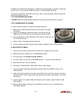
The Raider was designed to be carried by the two side rails installed 

to allow the outboard to be moved through submarine hatches and  
small areas.  The handle/shifter should be upright into the hollow area  
to keep from getting damaged and to help in carrying the Raider.  Be  
aware of the sharp propeller when lifting through submarine hatches. 


To move engine around shop area, use a motor stand that supports  
engine by the transom mount. 


b. Installation of single Engine 


The Raider has been designed to be released from submarines and air dropped.   This in-
stallation will discuss a typical installation 

– no special operations installation. 

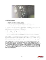
Position the outboard engine at the exact center of the stern and mount it against the Rub-
ber Inflatable Boat pad or plate.  It is important to keep it centered as much as possible, 
Tighten clamp screws by hand DO NOT use tools to tighten clamp screws.  Retighten en-
gine clamps after 15 minutes of operation. 


Hand Rails 

– Both Sides 

for Carrying 

WARNING 

Most Rubber Inflatable Boats are rated and certified in terms of 
their maximum horsepower on the transom.  This information is 
shown on the boat’s certification plate.  Do not equip your RIB with 
an outboard that exceeds this limit. 
 
Do not operate the engine until it has been securely mounted on 
the boat in accordance with the instructions.  Attach safety wire to 
boat to avoid losing the motor overboard. 

Summary of Contents for 50 HP TLDI

Page 1: ... Multi Fuel SubmersibleOutboard Motor This manual has been prepared for the United States Guardian Angels for service of the Multi fuel Submersible Outboard motor designed and manufactured under Contract No N61331 11 C 0008 dated 3 4 11 The data presented in this manual was revised as of August 2013 representing the latest revision 2013 ...

Page 2: ...ider Break in 9 c Normal Starting Procedure 9 d After Raider Starts Warm Up 10 e Forced engine oil feeding 10 f Idle Speed 10 g Throttle Friction 11 h Shifting 11 i Stopping Raider 12 j Trim Angle 12 k Trailering 12 l Tilting 12 m Trim Tab Adjustment 13 n Shallow Water Drive 13 o Shallow Water Operation 13 p Impact Damage 14 q Special Operating Conditions 14 r Overheating 14 s Emergency Starting 1...

Page 3: ...the instructions shown Of particular importance in formation preceded by the words or symbols draw attention to safety issues This man ual contains information that can help prevent personal injury and damage to equipment Understand the following symbols before proceeding Safety Warning Alerts you to the possibility of danger and identifies information that will help pre vent injuries Identifies i...

Page 4: ...of common 50 Raider outboards outside of engine block and heads The Raider 40 only has two cylinders weight under 150 pounds The Raider 50 40 offers multi fuel operation submersibility no battery required however this option of an enclosed battery with electric start under the cowling can be ordered pull start small enough to go through a submarine hatch and strong enough to operate after an air d...

Page 5: ...stem Through hub Lubrication system Oil injection Cooling system Water cooling Water temperature control Thermostat with pressure relief valve Ignition System Inductive Ignition timing control Electronics Control Unit ECU Firing Order 1 2 3 Spark Plug NGK PZFR6H Alternator 12V 280W Maximum Battery Not required optional lightweight lithium iron phosphate battery under cowl Trim Angle 4 24 degrees T...

Page 6: ...ion efficiency in the TLDI engine The result is better fuel economy lower maintenance ability to burn multi fuels and capable of submersion The air assisted Low pressure direct fuel injection process involves using an air com pressor to pressurize the fuel supplied by the fuel pump and inject it directly into the combustion cylinder in the form of a finely atomized mixture that achieves maximum co...

Page 7: ...5 g TLDI RAIDER Parts Identification 2 RAIDER A B C A Rear dewatering valve B Front dewatering valve C Mid dewatering valve ...

Page 8: ...is in stallation will discuss a typical installation no special operations installation Position the outboard engine at the exact center of the stern and mount it against the Rub ber Inflatable Boat pad or plate It is important to keep it centered as much as possible Tighten clamp screws by hand DO NOT use tools to tighten clamp screws Retighten en gine clamps after 15 minutes of operation Hand Ra...

Page 9: ...on dual motors for control and a cable inserted from one engine to the op posite for single power to both outboards d Installation of Safety Wire To prevent loss of engine engines overboard attach engine retention cable that is attached to the Raider outboard to the boat e Transom Height The Raider has been designed to have the anti ventilation plate at a level 10 to 30 mm 0 4 to 1 2 inches below ...

Page 10: ...mance the propeller should match the boat type and its load Replacing the propeller A worn or bent propeller will affect engine performance and may over time cause en gine trouble 1 Pull out the split pin and remove the pro peller nut and washer 2 Remove the propeller by pulling towards you 3 Apply grease to the propeller shaft before mounting the new propeller 4 Fit the washer securely tighten th...

Page 11: ...optimum performance The procedures we follow are shown below c Normal Starting Procedure Move the tilt run lever to RUN position Place engine in normal operating position Connect the fuel line connector from the tank to the engine s fuel connector Turn fuel line connector onto fuel tank connector If the fuel tank has a manual vent open it If you don t the engine will eventually die from fuel starv...

Page 12: ...water pump indicator is not discharging a steady stream of water STOP the engine when it is safe e Forced engine oil feeding When the engine is new or has been left without operation for a long time execute the following operation for forcedly feeding the engine oil to the oil line before starting the Raider Engine 1 Disconnect the link rod by turning the rod snap interlocking with the oil pump as...

Page 13: ... shift engine with throttle control advanced beyond the shift position Increase Speed Turn throttle control counterclockwise toward FAST toward you if seated in boat next to engine Decrease Speed Turn throttle control clockwise toward SLOW away from you if seated in boat next to engine Shift to NEUTRAL Turn throttle control clockwise to the SHIFT position or slower Move the shift lever to NEU TRAL...

Page 14: ...tical position For additional road clearance move angle adjusting rod to an outer stern bracket position Refer to Raider Trim Angle DO NOT use the tilt support as a Trailering bracket The engine should always be resting on the angle adjusting stop rod when under full power or when trailering l Tilting DO NOT push down on tiller handle to tilt engine Raise Raider 1 Move tilt run lever to the TILT p...

Page 15: ...propel ler or water pump damage 1 Place engine in shallow water drive position Refer to Shallow Wa ter Drive a DO NOT operate engine in REVERSE with the tilt run lever in the TILT position Engine can tilt up resulting in loss of control 2 Run at SLOW SPEEDS ONLY Check water pump indicator often Note Shallow water drive setting can be adjusted for different boat load conditions 3 Before operating i...

Page 16: ...ture is below 32 F 0 C When removing engine from water allow cooling system to drain completely by placing engine in upright position Weedy Water Weeds can block the water intakes and cause engine to overheat Weeds on the propeller will cause engine to vibrate Run at slow speeds and reverse engine frequently to clear weeds from propeller Check water pump indicator often Remove weeds from propeller...

Page 17: ...ine when it is safe DO NOT attempt to operate engine IF a steady stream of water is visible from the water pump indicator check to see if the re strictor is installed in the end of the water hose Without it the engine and ECU will over heat Continue to run engine at SLOW SPEED ONLY when it is safe until it returns to normal operating temperature If the engine overheats the cylinder and exhaust cov...

Page 18: ...led and cap tightened 5 Connect fuel line and pump primer bulb until firm resistance is felt to fill fuel system u Dewater Procedure 1 Connect the fuel line connector from the tank to the engine s fuel connector 2 Make sure that the shift lever is in the NEUTRAL position 3 Turn twist grip to the full open throttle position 4 Turn the 3 drain valve levers to the DRAIN position 1 4 turn counterclock...

Page 19: ...your mission and it cannot be serviced keep it submersed to avoid prolonged exposure to the atmosphere until it can be serviced If the Raider is brought on deck and it can t be operated or serviced keep it submerse in fresh water but get it prepared for your next mission as soon as possible If the RAIDER can be operated on deck dewater the engine following the procedures in De water Procedure oper...

Page 20: ...g engines Do not wear jewelry or loose clothing Keep hair hands and clothing away from rotating flywheel Replace any locking fastener locknut or patch screw if it s locking feature becomes weak Definite resistance to tightening must be felt or locking fastener is not suitable for continued use Replace only with authorized replacement part or equivalent a Fuel Oil Requirements ECU controlled oil pu...

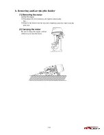
Page 21: ...19 b Removing and Carrying the Raider a ...

Page 22: ... moisture from metal surfaces It protects equipment and tools that are left outdoors even in humid coastal areas Anti Corrosion Spray dries out ignition systems to start wet engines and stops moisture induced short cir cuits in electrical systems e Optional Accessories 1 Both the 50 and 40 Horsepower can be purchased with a battery system that is enclosed under the cowling This battery is safe und...

Page 23: ... Fogging Oil and spray oil through the throttle plate 2 Stop engine and remove all spark plugs Spray Storage Fogging Oil into the spark plug holes 3 Pull starter to distribute the fogging oil throughout the cylinders Install and torque the spark plugs Leave spark plug leads disconnected to prevent accidental starting during storage 4 If the engine is removed from the boat examine all hardware you ...

Page 24: ... and fuel leakage under the engine cover Fire and explosion could occur 12 Replace engine cover Use touch up paint where needed 13 Coat all outside painted surfaces of engine with automotive wax 14 The engine must be stored in a normal vertical position on the boat or on an adequate engine stand h Out of Storage Service 1 Check gear case lubrication If leakage is evident gear case seals may need a...

Page 25: ...or your next mission Dewater the engine following the procedures in Dewater Procedure Operate the engine for approximately five minutes at full operating temperature with fresh water Whenever possible after use or submersion in sea water wash entire engine and powerhead with fresh water to remove salt deposits especially under the flywheel where the accumulation of deposits will build up Wipe down...

Page 26: ...24 Motor on Stand Back of Raider Front of Raider Top view of rear dewatering valve ...

Page 27: ... class Extensive modifications to commercial off the shelf outboard solely for the warfighters needs No bells and whistles o Rugged o Durable Originally designed for Japanese fisherman to work day in and day out World wide parts availability results in life cycle cost savings Most parts for the Raider 50 are common to the Raider 40 ...

Page 28: ...26 Robotics and Conceptual Engineering Inc 2702 Lake Dauterive Rd Loreauville LA 70552 337 577 6810 7887 Bryan Dairy Rd Largo FL 33777 321 403 3585 August 2013 ...

Reviews: