background image

MultiRAE 

User’s Guide 

15 

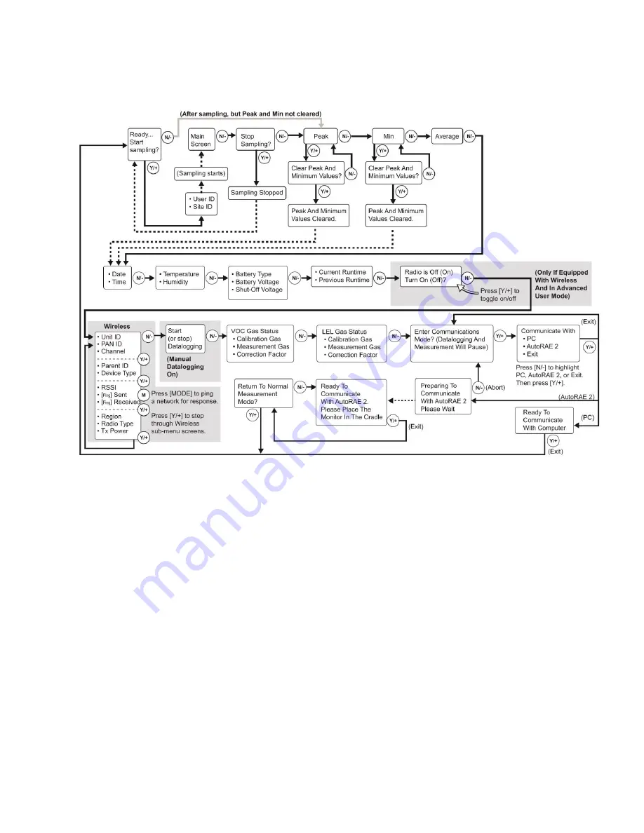
Search Mode 

Note:

 If the instrument is not equipped with a VOC sensor (PID), or is not equipped with an LEL sensor, 

then screens for those sensors (VOC Gas Status and LEL Gas Status, respectively) are not shown. 


Note:


Dashed line indicates automatic progression. 


WARNING! 

Gamma readings are not taken in Search Mode. 


Summary of Contents for MultiRAE

Page 1: ...MultiRAE User s Guide Rev D December 2013 P N M01 4003 000 ...

Page 2: ...ring your product you can Receive notification of product upgrades or enhancements Be alerted to Training classes in your area Take advantage of RAE Systems special offers and promotions IMPORTANT This User s Guide covers instruments with application firmware version 1 14 and sensor firmware version 1 04 2013 RAE Systems Inc ...

Page 3: ...22 5 7 Alkaline Battery Pack 22 6 Turning The MultiRAE On And Off 23 6 1 Turning The MultiRAE On 23 6 2 Turning The MultiRAE Off 23 6 3 Testing Alarm Indicators 24 6 4 Pump Status 24 6 5 Calibration Status 24 6 6 Bump Status 25 7 Modes Of Operation 26 7 1 Hygiene Operation Mode 26 7 2 Search Operation Mode 26 7 3 Basic User Mode 26 7 4 Advanced User Mode 26 8 Programming 26 8 1 Enter Programming I...

Page 4: ...oin Network 44 8 3 6 5 Interval 45 8 3 6 6 Off Network Alarm 45 8 3 6 7 Factory Reset 46 8 3 7 Monitor 46 8 3 7 1 LCD Contrast 46 8 3 7 2 Operation Mode 47 8 3 7 3 Pump Speed 47 8 3 7 4 Zero At Start 47 8 3 7 5 Fast Startup 47 8 3 7 6 Temperature Units 47 8 3 7 7 Language 47 8 3 7 8 Site ID 47 8 3 7 9 User ID 47 8 3 7 10 Date Format 48 8 3 7 11 Date 48 8 3 7 12 Time Format 48 8 3 7 13 Time 48 8 3 ...

Page 5: ... 5 3 Single Sensor Span Calibration 65 11 MultiRAE Pro Multi Threat Gamma Operation 66 11 1 Multi Threat Mode For Simultaneous Radiation Gaseous Threat Measurements 66 11 2 Gamma Radiation Only Measurement Mode 67 11 3 Gas Only Measurement Mode 69 12 Datalog Transfer Monitor Configuration and Firmware Upgrades Via Computer 71 12 1 Downloading Datalogs And Performing PC Based Instrument Configurati...

Page 6: ...MENT A ÉTÉ ÉVALUÉE CAUTION BEFORE EACH DAY S USAGE SENSITIVITY OF THE LEL SENSOR MUST BE TESTED ON A KNOWN CONCENTRATION OF METHANE GAS EQUIVALENT TO 20 TO 50 OF FULL SCALE CONCENTRATION ACCURACY MUST BE WITHIN 0 AND 20 OF ACTUAL ACCURACY MAY BE CORRECTED BY CALIBRATION PROCEDURE ATTENTION AVANT CHAQUE UTILISATION JOURNALIERE VERIFIER LA SENSIBILITE DU CAPTEUR DE LIE AVEC UNE CONCENTRATION CONNUE ...

Page 7: ...nd Canada PGM62xx is intrinsically safe and may be used in hazardous locations SUBSTITUTION OF COMPONENTS MAY IMPAIR INTRINSIC SAFETY MARKING The product is marked with the following information RAE SYSTEMS 3775 N 1st St San Jose CA 95134 USA Type PGM62x0 PGM 62x6 PGM 62x8 Serial No matrix XXX XXXX 000 IECEx SIR 11 0069X Ex ia IIC T4 Ga PGM62x0 PGM62x6 Ex ia d IIC T4 Gb PGM62x8 0575 SIRA 11ATEX215...

Page 8: ...ts at end of life This symbol crossed out wheeled bin indicates separate collection of waste electrical and electronic equipment in the EU countries This product may contain one or more Nickel metal hydride NiMH Lithium ion or Alkaline batteries Specific battery information is given in this user guide Batteries must be recycled or disposed of properly At the end of its life this product must under...

Page 9: ... 300 VOCs Technical Note TN 106 with ionization energies and correction factors for 300 VOCs Warranty registration card 10 charcoal filters reduce CO sensor s cross sensitivity to VOCs 10 charcoal filters reduce CO sensor s cross sensitivity to VOCs Ships in a hard transport case Ships in a Pelican case MultiRAE Lite Diffusion MultiRAE Lite Pumped MultiRAE Lite monitor with sensors battery and wir...

Page 10: ...rared PID photoionization detector and gamma radiation sensors to fit a wide variety of applications The MultiRAE family s wireless capability elevates worker protection to the next level by providing safety officers real time access to instrument readings and alarm status from any location for better visibility and faster response Notes NDIR combustible sensors are not supported on the diffusion ...

Page 11: ... driven user interface Simple maintenance with easily accessible sensors pump and plug and play battery Fully automated charging data management bump testing and calibration with AutoRAE 2 N key MODE key Gas inlet Display Alarm LEDs Alarm Buzzer Belt clip on back Alarm LED LED Y key External filter Charging and Communication Contacts The belt clip on the back of the pump equipped MultiRAE can be s...

Page 12: ... on pump equipped models Datalogging status shown when datalogging is on blank when off Battery status three segments show battery charge level Man Down alarm enabled Sensor due for calibration Sensor due for a bump test All sensors tested and calibrated to policy tick mark all sensors have been bump tested and calibrated no sensor is overdue for a bump test or calibration according to the interva...

Page 13: ...ane corresponds to the N key Here are examples that show the relationships of the keys and functions In addition to the functions described above any of the keys can be used to manually activate display backlighting Press any key when the backlighting is off to turn it on A subsequent key press is required to carry out an actual function corresponding to that key 3 1 3 LCD Flip The MultiRAE senses...

Page 14: ...2 3 1 4 Key Mapping When LCD Is Flipped When the instrument is inverted and the LCD flips the keys are mapped to the functions shown on the screen Display with MultiRAE in non inverted position Display with MultiRAE inverted ...

Page 15: ...utomatically reconfigured according to the number and types of sensors in the MultiRAE If the configuration includes five sensors and one of them is a PID then the lamp value 9 8eV or 10 6eV is shown along with the currently applied correction factor CF and measurement gas One sensor Two sensors Three sensors Four sensors Five sensors including Gamma radiation sensor Five sensors including PID sho...

Page 16: ...ou to save sample readings as individual events in the datalog You can also clear peak and minimum values Note You can switch between Hygiene and Search modes via the Programming Menu Select Monitor and then Operation Mode Note If the instrument is not equipped with a VOC sensor PID or is not equipped with an LEL sensor then screens for those sensors VOC Gas Status and LEL Gas Status respectively ...

Page 17: ...not equipped with a VOC sensor PID or is not equipped with an LEL sensor then screens for those sensors VOC Gas Status and LEL Gas Status respectively are not shown Note Dashed line indicates automatic progression WARNING Gamma readings are not taken in Search Mode ...

Page 18: ...will route from Ready Start sampling directly to Date and Time if you press N see red line in diagram below until you perform a new sample Also if you start sampling again and stop sampling clear the Peak or clear the Min it advances to Date and Time as well Note Dashed line indicates automatic progression WARNING Gamma readings are not taken in Search Mode ...

Page 19: ...nique identifier of the instrument s radio Pan ID and Channel are read only parameters that help you to check whether the instrument s wireless settings are correct very helpful for troubleshooting The next page Parent ID and Device Type are also read only The Parent ID the ID of the Parent wireless device to which the monitor is connected is not changeable The device type tells you that it is Sta...

Page 20: ... wipe them with a soft dry cloth Do not use solvents or cleaners WARNING To reduce the risk of ignition of hazardous atmospheres recharge remove or replace the battery only in an area known to be non hazardous Do not mix old and new batteries or batteries from different manufacturers 5 1 Charging With The MultiRAE Desktop Cradle Follow this procedure to charge the MultiRAE 1 Plug the AC DC adapter...

Page 21: ...ith The Travel Charger The Travel Charger is a lightweight portable alternative to the Desktop Cradle for charging and PC communications Follow these steps to use the Travel Charger Before attaching the Travel Charger check that it is aligned correctly with the base of the MultiRAE There are two alignment pins on one side and one alignment pin on the other side designed to mate with matching point...

Page 22: ...face to accept the Truck Mount The maximum screw diameter must not exceed 6 4mm 0 25 Vertical clearance should be at least 26cm 10 Letter Measurement A 61 6 mm 2 42 B 96 mm 3 8 C 113 mm 4 5 D 150 8 mm 6 Once the Truck Mount is attached disconnect the front part of the Desktop Cradle from its base by pressing on the rubber release buttons on both sides of the cradle Next insert the plug from the po...

Page 23: ...battery can be charged by placing the monitor in an AutoRAE 2 Cradle Details are covered in the AutoRAE 2 User s Guide 5 5 Replacing A Battery The MultiRAE battery packs are plug and play and can be replaced on the go without tools To replace the MultiRAE battery 1 Remove the battery from the instrument by sliding the tab and tilting out the adapter Note The belt clip and rubber boot are removed i...

Page 24: ...ne batteries use only Duracell MN1500 and provides approximately 8 hours of normal operation Note The vibration alarm is disabled whenever the alkaline adapter is used To replace the alkaline adapter s batteries 1 Remove the hex socket screw at the end of the adapter 2 Lift the cover off the battery compartment 3 Insert four fresh AA batteries as indicated by the polarity markings 4 Replace the co...

Page 25: ...orcement settings whether calibration and or bump testing are enforced Note To speed up the startup time the number of screens shown on startup can be reduced by enabling the Fast Startup option under Programming Monitor Then the MultiRAE s main reading screen appears It may take a few minutes for sensors to show a reading so if any have not warmed up by the time the main screen is shown you will ...

Page 26: ... you see this icon blinking on and off Once the obstruction is removed you can try to restart the pump by pressing the Y If the pump does not restart and the pump stall alarm continues consult the Troubleshooting section of this guide or contact RAE Systems Technical Support It is advisable to perform a pump stall test periodically to make sure the pump is working properly and there are no leaks i...

Page 27: ... next to the sensor that requires bump test A bump test is required and indicated by this icon if The defined period of time between bump tests has been exceeded bump test overdue The sensor has failed a previous bump test The sensor s should be challenged on a periodic basis ...

Page 28: ...personnel 7 4 Advanced User Mode In Advanced User Mode there are no access restrictions you do not need a password and MultiRAE provides the indications and data you need most for typical monitoring applications 8 Programming The menu in Programming Mode is to adjust settings calibrate sensors and initiate communication with a computer It has the following submenus Calibration Measurement Alarms D...

Page 29: ...g N and then using Y to change the number in each position Note The default password is 0000 Note The password screen only appears when you enter the Programming Mode the first time after turning the instrument on in Basic Mode If you have input the correct password you do not have to input it again to enter Programming Mode until you turn the instrument off and on again Once you enter Programming...

Page 30: ...ump equipped version only This menu item is shown only if a 3 point calibration is enabled Change Span2 Value menu item is only shown if a 3 point calibration is enabled on the instrument Three point calibration is disabled by default but can be enabled on MultiRAE and MultiRAE Pro instruments with 10 6eV PID sensors including high range ppm and ppb PID sensors The MultiRAE Lite PID sensor only su...

Page 31: ...n is performed on all enabled gas sensors at the same time To perform Fresh Air calibration on multiple sensors 1 If using dry air install the calibration adapter and connect it to a source of dry air Otherwise do not use calibration adapter to perform fresh air calibration 2 At the Calibration Menu select Fresh Air Press Y once to enter the fresh air calibration sub menu 3 Start the flow of dry a...

Page 32: ...n at any time during the countdown by pressing N 6 If the calibration is not aborted the display shows the sensor names and tells you whether the calibration passed or failed followed by the sensor readings 8 3 2 3 Single Sensor Zero This allows you to perform zero fresh air calibration on individual sensors Even though most toxic gas sensors can be zeroed in fresh air sensors such as the CO2 and ...

Page 33: ... multiple sensors simultaneously you can select a single sensor and perform a span calibration Note If a calibration icon bottle with bottom portion filled in is shown next to any of the sensors it means that the sensor is due for a full calibration To perform span calibration of an individual sensor follow these steps 1 At the Calibration Menu select Single Sensor Span 2 Select a sensor to calibr...

Page 34: ...on the rubber boot that marks where the sensor is located inside the instrument 8 3 2 5 Multi Sensor Bump Depending on the configuration of your MultiRAE and span gas you have you can perform a bump test simultaneously on multiple sensors Which sensors are bump tested simultaneously is defined in the Multi Cal Select menu Refer to section 8 3 2 9 for more information In case all sensors in the ins...

Page 35: ...ation is not aborted the display shows the sensor names and tells you whether the calibration passed or failed followed by the sensor readings 7 If a sensor requires different gas such as a PID for VOCs you are prompted Change the calibration gas and when you are ready start bump testing by pressing Y Note You can quit the bump calibration procedure and exit to the menu whenever you see Quit Press...

Page 36: ...calibration adapter and connect it to a source of calibration gas 4 Verify that the displayed calibration value meets the concentration specified on the gas cylinder 5 Start the flow of calibration gas 6 Press Y to start calibrating or wait for calibration to start automatically 7 A countdown screen appears You can abort the calibration at any time during the countdown by pressing N 8 If the calib...

Page 37: ...d correction factor CF 8 3 2 9 Multi Cal Select This menu allows you to define a group of sensors to be bump tested and span calibrated together Simultaneous testing and calibration of multiple sensors shortens the bump test and calibration processes and reduces the number of individual gas cylinders you need For example it may be more efficient to use a single cylinder with a four gas mix includi...

Page 38: ...e 8 3 2 11 Change Span2 Value If your MultiRAE is equipped with a high range or parts per billion PID sensor you can set the span gas value for a third calibration point Span2 The unit of measure is shown on the display 1 Press Y to select the highlighted sensor VOC 2 Press N to step through the digits 3 Press Y to increase the number from 0 through 9 Once the number 9 is reached pressing Y causes...

Page 39: ...Scroll down the list of sensors using the N key 2 Add or remove that gas from the list by pressing Y An X in a box to the left of a sensor s name indicates it is selected 3 Once you have made all your selections press MODE for Done 8 3 3 2 Change Meas Gas The MultiRAE has extensive onboard gas libraries for combustible gases and VOCs that you can use to configure your MultiRAE to automatically app...

Page 40: ...list of the last ten gases used by your instrument The list is built automatically and is only updated if the gas selected from Custom Gases or Library is not already in the Last Ten This ensures that there is no repetition Gas Library is a library that consists of more than 200 gases for the PID sensor and more than 50 for the catalytic LEL sensor Custom Gases are gases with user modified paramet...

Page 41: ...d milliGrays Gamma The CO2 switch point from ppm to VOL can be changed via ProRAE Studio 2 Here are two examples of menu hierarchies select the sensor type and then the measurement unit 8 3 4 Alarms Use this menu to change high low STEL and TWA alarm limits the points at which alarms are triggered The Alarms menu also allows changing alarm mode latched or automatic reset and alarm output methods c...

Page 42: ...ument is motionless when it is not supposed to be something wrong may be happening to its user If that is the case a wirelessly enabled MultiRAE not only goes into alarm locally on the instrument to notify people in the vicinity but also remotely over the RAE Systems Dedicated Wireless Network to transmit the alarm to remote safety officers at a command center that a person is down so that help ca...

Page 43: ...countdown answering the Are You OK question with No the Man Down alarm starts If wireless connectivity is enabled a Man Down message is also sent to remote observers IMPORTANT When gas or radiation alarm conditions exist at the same time as the Man Down is activated the pre alarm stage is skipped and the instrument goes straight into a Super Alarm gas or radiation and Man Down with four beeps flas...

Page 44: ...og information every time the instrument is sampling until the datalog memory is full Manual Datalogging occurs only when you manually initiate it see below for details Snapshot Captures a single event when you press MODE Note You can only choose one datalog type to be active at a time About Manual Datalogging When the instrument is set to Manual Datalog you can turn datalogging on and off by repe...

Page 45: ... Memory Full Action When the internal datalog memory is full the MultiRAE can either stop collecting data Stop when full or go back to the beginning and overwrite the data from the first entry second entry etc Wraparound 8 3 6 Wireless When a MultiRAE is equipped with a wireless modem its settings are controlled via the menu items under Wireless 8 3 6 1 Radio ON OFF Turn the radio on or off via th...

Page 46: ...tiRAE and any other devices that you want to interconnect wirelessly must be operating on the same channel 1 Press Y to increase the number and N to advance to the next digit 2 After moving to the last digit and making changes press MODE Press Y to save the change Press N to undo the change 8 3 6 4 Join Network You can tell the MultiRAE to automatically join a network with a certain PAN ID without...

Page 47: ...ns The interval can be set to 10 30 60 120 or 240 seconds 1 Scroll down the list of intervals by pressing N until the interval you want is highlighted 2 Select the highlighted interval by pressing Y 3 Save or register the change Press Y to save the change Press N to undo the change Note The default interval is 30 seconds 8 3 6 6 Off Network Alarm If you would like the MultiRAE to notify you when i...

Page 48: ...you reach the last one it returns to the first selection 8 3 7 1 LCD Contrast The display s contrast can be increased or decreased from its default setting You may not need to ever change the default setting but sometimes you can optimize the display to suit extreme temperature and ambient brightness darkness conditions Use the Y and N keys to decrease or increase LCD contrast respectively the bar...

Page 49: ...libration press MODE to bypass it If you start a zero calibration and want to abort it press N and the calibration stops and the main display is shown 8 3 7 5 Fast Startup Fast Startup reduces the amount of time between when the instrument is turned on and is ready for use It skips showing you many settings and is best suited to environments where the MultiRAE is turned on and off very often durin...

Page 50: ... Two User Modes are available Advanced and Basic The Advanced User Mode allows a greater number of parameters to be changed than Basic User Mode It can be used with either of the Operation Modes Hygiene or Search No password is required to enter the Programming Menu when in Advanced User Mode 8 3 7 15 Backlight The display s backlight can be set to illuminate either automatically based on ambient ...

Page 51: ...ey are shown in sequence Note Policy enforcement features are disabled by default 9 1 Setting Policy Enforcement You must use ProRAE Studio II to make changes to Policy Enforcement settings The procedure differs depending on whether you are using an AutoRAE 2 a MultiRAE Travel Charger or a MultiRAE Desktop Cradle Policy violations are captured in the datalog 9 1 1 Using The AutoRAE 2 Automatic Tes...

Page 52: ...In ProRAE Studio II the AutoRAE 2 Cradle is shown including its Serial Number under Online 9 Expand the view to show the MultiRAE in the AutoRAE 2 Cradle by clicking the to the left of the image of the AutoRAE 2 Cradle 10 Double click on the icon representing the MultiRAE 11 Click Setup ...

Page 53: ...e instrument Can Bypass If calibration is due but the user does not want to perform a calibration the instrument can still be used In this case the instrument records that the user has bypassed the calibration requirement in a Policy Violation report Must Bump The user is prompted to bump test the instrument when a bump test is due as set by the bump test interval There are two programmable option...

Page 54: ...ng down 16 Once you have made your selections in ProRAE Studio II you must upload the changes to the instrument Click the icon labeled Upload all settings to the instrument 17 A confirmation screen is shown Click Yes to perform the upload or No to abort Uploading takes a few seconds and a progress bar is shown You can abort the upload by clicking Cancel 18 Exit ProRAE Studio II 19 Press Y on the M...

Page 55: ...options PC AutoRAE 2 Exit 6 With PC highlighted press Y to select it The screen now displays Ready To Communicate With Computer 7 Start ProRAE Studio II 8 Select Administrator 9 Input the password the default is rae 10 Click OK 11 Click A detects instruments automatically 12 Click on the instrument s icon when it appears to highlight it 13 Click Select 14 Click Setup 15 Click Policy Enforcement Th...

Page 56: ...ge 49 for details 9 2 2 MultiRAE Desktop Cradle Or Travel Charger If the MultiRAE screen displays the message that it must be bump tested or calibrated and if the option to bypass bump testing or calibration is not available you should shut off the instrument and follow the procedure outlined here if you want to change the Policy Enforcement settings 1 Use a USB cable to connect the MultiRAE in it...

Page 57: ...k Setup 14 Click Policy Enforcement The Policy Enforcement pane is shown 15 Deselect Policy Enforcement features you do not wish to use 16 Click Upload all settings to the instrument 17 When you see this confirmation Click Yes Uploading will take a few seconds and this progress bar is shown 18 When the upload is done exit ProRAE Studio II 19 Press Y on the MultiRAE to exit Communication Mode ...

Page 58: ...ing on use and sensor exposure to poisons and contaminants Calibration and bump test intervals and procedures may vary due to national legislation A bump test or calibration can be performed either manually or using the AutoRAE 2 Automatic Test and Calibration System When a bump test or calibration is done manually the instrument makes a pass fail decision based on sensor performance but the user ...

Page 59: ... VOC test gas to test the PID sensor and another with a 4 gas mix to test electrochemical such as CO H2S and O2 and LEL sensors As with calibration the instrument intelligently splits the process into two consecutive steps first the wizard prompts for testing electrochemical and LEL sensors and then it tests the PID sensor For a manual bump test a constant flow regulator producing 0 5 to 1 liters ...

Page 60: ...start the bump test While the bump test is being performed the readings for each sensor are shown Once the bump test completes pass fail test results and readings are shown for each sensor Note If a PID or other sensors are installed in the instrument require a dedicated cylinder of gas to calibrate the instrument will prompt for calibrating such sensors at this point 5 If a PID or other sensors i...

Page 61: ...alibration the instrument is now ready for use Note When a manual bump test is performed the readings shown are in the equivalent units of the calibration gas and not the measurement gas if different 10 2 4 Testing The Gamma Radiation Sensor The gamma radiation sensor does not require user calibration You can check it by placing a check source on the rear of the MultiRAE equipped with a gamma sens...

Page 62: ...A CO2 Sensor Important If your MultiRAE is equipped with a CO2 sensor it must be zero calibrated using 100 Nitrogen N2 which is inert instead of fresh air or zero air 10 3 2 Zero Calibration For Parts Per Billion ppb Sensor Important The parts per billion PID sensor for volatile organic compounds VOCs should not be zeroed in fresh air VOCs are normally present in ambient air so zeroing the sensor ...

Page 63: ...abled by default but can be enabled using ProRAE Studio II Instrument Configuration and Data Management software on MultiRAE and MultiRAE Pro instruments with 10 6eV PID sensors including high range ppm and ppb PID sensors The MultiRAE Lite PID sensor does not support three point calibration Default calibration gas settings for MultiRAE PID sensors are as follows Sensor Specifications Zero Span Sp...

Page 64: ...harger or AutoRAE 2 and must be in the PC or AutoRAE 2 communications mode 1 Start up the ProRAE Studio II software enter a password and detect the instrument following the directions provided in the ProRAE Studio II User s Manual 2 Click Setup to download the MultiRAE s current configuration information 3 Click Sensor Summary to show the list of installed sensors ...

Page 65: ...should now be showing 6 Click the Upload all settings to the instrument icon You will be asked whether you want to upload all configurations to the instrument Click Yes 7 When you are done quit ProRAE Studio II and then press Y on the MultiRAE to exit the PC communications mode The instrument returns to operating in Normal mode ...

Page 66: ...A calibration cap must not be used Teflon tubing must be used to test or calibrate the PID sensor Follow the steps described here to perform a multi sensor span calibration 1 Attach the calibration adapter and connect gas to the MultiRAE 2 Start the flow of gas and then either press Y to begin calibration or wait for calibration to start automatically once the sensor senses the gas A countdown scr...

Page 67: ... value meets the concentration label on the gas cylinder 5 Start the flow of calibration gas 6 Press Y to start calibrating You can abort the calibration at any time during the countdown by pressing N After a timer countdown the span calibration is done The LCD will display whether the calibration was successful and the reading for that calibration gas Note If the sensor calibration fails try agai...

Page 68: ...ped with a gamma radiation sensor provided the gamma sensor is enabled The minimum instrument firmware requirements for the gamma sensor are Application firmware v 1 14 or higher Sensor firmware v 1 04 or higher When the monitor is turned on it boots up in multi threat mode to monitor for both gamma radiation and gaseous threats Measurements are done in sequence Gas measurements are taken first fo...

Page 69: ...operation in multi threat mode during the part of the cycle in which the pump is turned off the PID sensor lamp is automatically cleaned by ozone that forms above the PID lamp crystal this ozone is removed by the air flow when the pump is running This auto clean feature reduces PID sensor maintenance frequency 11 2 Gamma Radiation Only Measurement Mode When the instrument is in gamma only mode gas...

Page 70: ...xit gamma only mode and either switch back to multi threat mode where both gamma radiation and gaseous threats are measured or to gas only mode 1 Press N when the instrument is running in gamma only mode 2 The following screen appears Press Y to enter normal multi threat mode Press MODE to enter gas only mode ...

Page 71: ... measurements are not taken The pump runs constantly as illustrated below MultiRAE Pro Operation in Gas Only Mode WARNING Gamma radiation cannot be detected by the MultiRAE when it is operated in gas only mode Activating Gas Only Measurement Mode To activate gas only measurement mode 1 Press N when the instrument is running in normal multi threat mode 2 Press MODE when the following screen appears...

Page 72: ...he gamma radiation sensor is always disabled when the MultiRAE Pro is used in Search Mode Radiation dose is not calculated for the gamma sensor If the monitor runs in gamma only mode for over 20 minutes TWA is not calculated for gas sensors STEL is reset for gas sensors when the instrument exits gamma only mode PID sensor auto cleaning is only performed in multi threat mode and is not available in...

Page 73: ...ust be in the PC or AutoRAE 2 communications mode Desktop Cradle or Travel Charger 1 Use the supplied PC Communications Cable USB to mini USB cable to connect the Desktop Cradle or Travel Charger to a PC 2 Turn on the MultiRAE Make sure it is running in Normal mode with the main measurement screen showing 3 Insert the MultiRAE in the Desktop Cradle or connect it to the Travel Charger 4 Activate th...

Page 74: ...e and one alignment point on the other side designed to mate with matching points on the bottom of the MultiRAE 4 Press in on the capture mechanism to lock the MultiRAE in place 5 Start up the ProRAE Studio II software enter a password and detect the instrument following the directions provided in the ProRAE Studio II User s Guide 6 Follow the instructions in the ProRAE Studio II User s Guide to d...

Page 75: ...ully slide the boot upward and slide it over the D ring and clamp 13 2 Replacing The Filter s Pumped Version If a filter is dirty or clogged remove it by unscrewing it from the black gas inlet adapter Discard it and replace it with a new filter Perform a pump stall test to make sure the inlet and the external filter are installed properly so that there are no leaks in the system Diffusion Version ...

Page 76: ...AE They are accessed by removing the cover that is held on by four screws 1 Turn off the instrument 2 Remove the four screws holding the sensor compartment 3 Remove the cover The sensors are plugged into the slots 4 Gently lift out the desired sensor module with your fingers 5 Install the replacement sensor It can only go into its slot one way The connector inside the MultiRAE and the indexing gui...

Page 77: ... replacement for example because the lamp does not illuminate or the sensor repeatedly fails calibrations place a new module into the slot being careful to match the indexing keys The sensor can only go into its slot one way 6 If you want to open the sensor module to inspect and clean the lamp and sensor electrode panel you must use the special tool part number G02 0306 003 package of three Its C ...

Page 78: ...not touch the lamp window with your fingers as the residual oils will affect its performance and shorten its life 12 Inspect the electrical contacts Clean them with a swab dipped in lamp cleaner if they appear to need cleaning 13 Reassemble the sensor module by placing the sensor electrode panel back in place and firmly pressing the cap back onto the top 14 Place the sensor module back into the Mu...

Page 79: ...crews 3 Lift off the metal bracket 4 Pressing down on the gas plate with one hand disconnect the pump from internal tubing by gently pulling it out It has an inlet and outlet that are held in the two holes with rubber gaskets to the left of the pump cavity 5 Press a new pump into place a small amount of wiggling helps making sure that both the inlet and outlet from the pump go into the two holes 6...

Page 80: ... the MultiRAE user and a remote safety officer if wireless is enabled of the alarm condition In addition to gas and radiation alarms Man Down and other alarms are available Furthermore the MultiRAE alarms if one or more of the following conditions occurs battery voltage low pump blocked PID lamp failed etc When the low battery alarm occurs there may be approximately 10 minutes of operating time re...

Page 81: ... 400ms 0 On STEL 1 beep sec STEL at sensor location 400ms Reading On TWA 1 beep sec TWA at sensor location 400ms Reading On Calibration Fail 1 beep sec Cal at sensor location 400ms Reading On Bump Fail 1 beep sec Bump at sensor location 400ms Reading On Datalog Full 1 beep sec Blinking datalog symbol 400ms Reading On Calibration Required Full Bottle symbol Reading Bump Required Empty Bottle symbol...

Page 82: ...ding On G6 6 beeps 40ms sec G5 5 beeps 50ms sec G4 4 beeps 60ms sec G3 3 beeps 70ms sec G2 2 beeps 80ms sec G1 Low 1 beep 90ms sec Negative 1 beep sec Neg at sensor location 400ms 0 On STEL 1 beep sec STEL at sensor location 400ms Reading On TWA 1 beep sec TWA at sensor location 400ms Reading On Calibration Fail 1 beep sec Cal at sensor location 400ms Reading On Bump Fail 1 beep sec Bump at sensor...

Page 83: ...eds TWA limit 1 Beep flash per second STEL Gas exceeds STEL limit 1 Beep flash per second Crossed pump icon flashes Inlet blocked or pump failure 3 beeps flashes per second Lamp flashes PID lamp failure 3 beeps flashes per second Empty battery icon flashes Low battery 1 flash 1 beep per minute CAL Calibration failed or needs calibration 1 beep flash per second NEG True sensor reading is below zero...

Page 84: ...ff Call authorized service center Lamp message when power on Lamp alarm Reasons Low ion concentration inside PID lamp especially in cold environment when first powered on Defective PID lamp or defective circuit Solutions Turn the unit off and back on Replace UV lamp Pump failed message Pump alarm Reasons Inlet probe blocked Direct connection to a gas outlet while the gas value is turned off Water ...

Page 85: ...d reception quality STEL TWA peak and minimum values Various instrument status related information Keypad 3 operation and programming keys MODE Y and N Sampling Built in pump or diffusion Average flow rate pumped 250 cc min Auto shutoff in low flow conditions Calibration Automatic with AutoRAE 2 Test and Calibration Station or manual Alarms Wireless remote alarm notification multi tone audible 95 ...

Page 86: ...PGM62x0 PGM62x6 IECEx SIR 11 0069X Ex ia d IIC T4 Gb for PGM62x8 CE Compliance European Conformity EMC directive 2004 108 EC R TTE directive 1999 5 EC ATEX directive 94 9 EC FCC Compliance FCC Part 15 Performance Tests LEL CSA C22 2 No 152 ISA 12 13 01 Languages Arabic Chinese Czech Danish Dutch English French German Indonesian Italian Japanese Korean Norwegian Polish Portuguese Russian Spanish Sw...

Page 87: ...e CO Hydrogen Sulfide H2S Combo 0 to 500 ppm 0 to 2 000 ppm 0 to 2 000 ppm 0 to 500 ppm 0 to 200 ppm 1 ppm 10 ppm 10 ppm 1 ppm 0 1 ppm Chlorine Cl2 0 to 50 ppm 0 1 ppm Chlorine Dioxide ClO2 0 to 1 ppm 0 03 ppm Ethylene Oxide EtO A Ethylene Oxide EtO B Ethylene Oxide EtO C Ext Range 0 to 100 ppm 0 to 10 ppm 0 to 500 ppm 0 5 ppm 0 1 ppm 10 ppm Formaldehyde HCHO 0 to 10 ppm 0 01 ppm Hydrogen H2 0 to ...

Page 88: ...Ethanol 59 1 7 Isopropanol 38 2 6 Acetone 45 2 2 Methyl Ethyl Ketone 38 2 6 Ethyl Acetate 45 2 2 Carbon Monoxide 75 1 2 Hydrogen 91 1 1 Ammonia 125 0 80 Response of the RAE Systems LEL sensor to a range of gases at the same LEL expressed as percent of methane response 100 These figures are for guidance only and are rounded to the nearest 5 For the most accurate measurements the instrument should b...

Page 89: ...s the year of manufacture For example M indicates the manufacturing year is 2010 First digit Year J 2008 K 2009 M 2010 N 2011 P 2012 Q 2013 R 2014 S 2015 T 2016 U 2017 V 2018 W 2019 17 Technical Support To contact RAE Systems Technical Support Team Monday through Friday 7 00AM to 5 00PM Pacific US Time Phone toll free 1 888 723 4800 Phone 1 408 952 8461 Email tech raesystems com ...

Page 90: ...systems com RAE Systems Europe ApS Kirstinehøj 23 A DK 2770 Kastrup Denmark Phone 45 86 52 51 55 Fax 45 86 52 51 77 orders raeeurope com sales raeeurope com service raeeurope com Web www raesystems eu RAE Systems UK Ltd D5 Culham Innovation Centre Culham Science Centre Abingdon Oxon OX14 3DB United Kingdom Phone 44 1865408368 Fax 44 1235531119 Mobile 44 7841362693 Email raeuk raeeurope com RAE Sys...

Page 91: ...il orders raeeurope com RAE Middle East LOB 7 Ground Floor Office 19 Jebel Ali Free Zone Dubai United Arab Emirates Phone 971 4 887 5562 Email mesales raesystems com RAE Systems Hong Kong Ltd Room 8 6 F Hong Leong Plaza 33 Lok Yip Road Fanling N T Hong Kong Phone 852 2669 0828 Fax 852 2669 0803 Email hksales raesystems com RAE Systems Japan Marunouchi Nakadori Bldg 6F 617 B 2 3 Marunouchi 2 Chome ...

Page 92: ......

Page 93: ...Rev D December 2013 P N M01 4003 000 ...

Reviews: