889-3819-00
MMU2-1600GE series Operations Manual Rev Apr 2020 Page
46
of 51
4.6.5.4
OTHER AC AND MISCELLANEOUS INPUTS
This display shows the current AC line voltage and frequency, Red Enable voltage, samples taken of every AC
input per line cycle, temperature, and Port 1 errors since midnight or the last reset (whichever came last). This
display is view only. Press the
ENTER
pushbutton or the
ESCAPE
pushbutton to exit.
4.6.5.5
DC INPUTS
This display shows the current status of the monitor DC Inputs. The voltage is shown for +24V Monitor I, +24V
Monitor II, +24V Inhibit, CVM, Type Select, Local Flash, External Reset, and the External Watchdog inputs.
Status of the Port 1 Disable is displayed. This display is view only. Press the
ENTER
pushbutton or the
ESCAPE
pushbutton to exit.
4.6.6
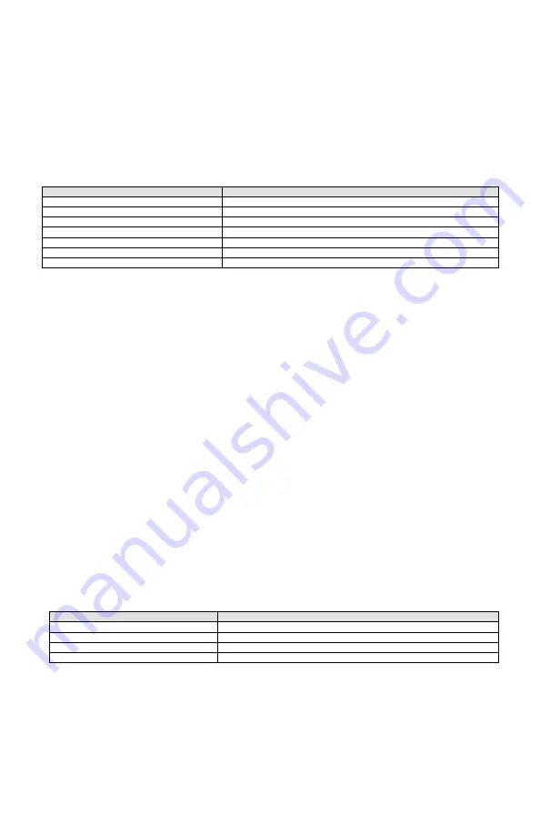
DIAGNOSTIC INFO
MENU TEXT
MENU FUNCTION
LED TEST
Run front panel LED diagnostic routine.
SCREEN TEST
Run display screen diagnostic routine.
FAULT CODES
View various monitor fault codes.
SDLC FRAMES
Access the menu for displaying various SDLC frame buffers.
FIRMWARE
View the firmware versions and dates.
STATS
Access the menu for displaying various operational statistics.
FACTORY
Access the menu for factory diagnostic information.
4.6.6.1
LED TEST SETTINGS
Use the up (▲) or down (▼) pushbutton to navigate between fields. Use the left (◄) or right (►) pushbutton to
change the selected setting. Press the
ENTER
pushbutton or
ESCAPE
pushbutton to exit.
TEST SPEED – Values between
000
and
127
use the standard test pattern. Values between
128
and
253
use a
simulated eight phase intersection with pedestrians pattern.
254
will turn all LEDs on and leave them on.
255
will
turn all LEDs off and leave them off. A smaller number indicates a faster speed for the test pattern.
LED TEST – When set to
ON,
the appropriate test patterns will be displayed on the front panel LEDs overriding
the normal display.
NOTE: In most instances, once the LED Test has been completed, the function should be turned OFF. If the LED
Test has been left ON, repeat the procedure outlined above or press the RESET pushbutton to turn the function
OFF.
4.6.6.2
SCREEN TEST
Use the up (▲) or down (▼) pushbutton to navigate between fields. Use the left (◄) or right (►) pushbutton to
change the selected setting. Press the
ENTER
pushbutton or
ESCAPE
pushbutton to exit.
TEST SPEED – Values between
001
and
023
can be selected. A smaller number indicates a faster speed for the
test pattern.
SCREEN TEST – When set to
ON,
the test patterns will be displayed until the
ENTER
or
ESCAPE
pushbutton is
pressed to cancel the Screen Test.
4.6.6.3
FAULT CODES
This display shows the values for Global Faults, Boot Diagnostic Faults, 186 Diagnostic Faults, DSP Diagnostic
Faults, DSP Transfer Faults, and Shift Error Faults. If you experience a Diagnostic fault, record all of the values
on this screen and contact Reno A&E Tech Support for guidance. This display is view only. Press the
ENTER
pushbutton or the
ESCAPE
pushbutton to exit.
4.6.6.4
DIAGNOSTIC SDLC FRAMES MENU
MENU TEXT
MENU FUNCTION
VIEW FRAME 0 DATA
View SDLC Frame 0 data.
VIEW FRAME 9 DATA
View SDLC Frame 9 data.
VIEW FRAME 129 DATA
View SDLC Frame 129 data.
VIEW FRAME 131 DATA
View SDLC Frame 131 data.
These displays shows the data of the last valid SDLC frame received (frame 0 or 9) or the data that will be
transmitted if an SDLC frame request (frame 129 or 131) is received by the monitor. This information is displayed
in hex format. The
ENTER
pushbutton will toggle the display between the hex mode and an ASCII mode. This
display is view only. Press the
ESCAPE
pushbutton to exit. Press the
HELP
pushbutton to view the data
organization within each frame.
4.6.6.5
FIRMWARE VERSIONS
This display shows the currently installed firmware versions and release dates for the primary bootloader
(BOOT1), secondary bootloader (BOOT2), main monitor code (MAIN), AC signal processor (DSP), and DC
signal processor (DC). This display is view only. Press the
ESCAPE
pushbutton to exit.


