background image

RADWIN


2000


C


Plus


User


Manual

Release


3.5.70

6

3

Setting


the


connected


ODU


as


Master


ODU

Chapter


6

This


window


enables


you


to


switch


between


HSU


mode


(Link


Slave


ODU)


and


HBS


mode


(Link


Master


ODU).


Click


the


HBS


button.


At


the


confirmation


popup


window,

click


OK


to


continue.


A


further


confirmation


is


displayed:

Dismiss


it


with


OK.


After


a


few


moments,


the


main


window


changes


appearance


completely


from


Figure 6

1


above:

Summary of Contents for 2000 C PLUS

Page 1: ...USER MANUAL RADWIN 2000 C PLUS POINT TO POINT BROADBAND WIRELESS Release 3 5 70...

Page 2: ...bited from and shall not directly or indirectly develop market distribute license or sell any product that supports substantially similar functionality based or derived in any way from RADWIN products...

Page 3: ...ease 3 5 70 ii Windows 2000 XP Pro Vista Windows 7 and Internet Explorer are trademarks of Microsoft Inc Mozilla and Firefox are trademarks of the Mozilla Foundation Other product names are trademarks...

Page 4: ...mail salesmx radwin com RADWIN Peru Av Antares 213 Lima 33 Peru Tel 511 6285105 Fax 511 990304095 Email salespe radwin com RADWIN India E 13 B 1 Extn Mohan Co operative Industrial Estate New Delhi 110...

Page 5: ...y to correct the interference by one or more of the following measures Reorient or relocate the receiving antenna Increase the separation between the equipment and receiver Connect the equipment into...

Page 6: ...must be considered during installation Caution Outdoor units and antennas should be installed ONLY by experienced installation professionals who are familiar with local building and safety codes and w...

Page 7: ...htning and power conductors in accordance with NEC Sections 725 54 c and 800 30 In all other cases an appropriate Listed Primary Protector must be provided Refer to Articles 800 and 810 of the NEC for...

Page 8: ...r 10 Hub Site Synchronization Chapter 11 Using the RADWIN GSU Part 3 Advanced Installation Topics Chapter 12 Reserved Chapter 13 VLAN Functionality with RADWIN 2000 C Plus Chapter 14 False Radar Mitig...

Page 9: ...verview 4 1 What s in the box 4 2 Tools required for installation 4 9 Safety Practices and Provisions 4 10 Hardware Installation Workflow for a RADWIN 2000 C Plus link 4 11 Towards Establishing a Link...

Page 10: ...ion 10 1 Hardware Installation 10 3 ODU HSS Unit Connection Pinout 10 7 Radio Frame Pattern RFP 10 7 link Configuration and HSS 10 9 Chapter 11 Using the RADWIN GSU What is it for 11 1 GSU Functionali...

Page 11: ...trum View Data stored 19 2 Spectrum View Main Window 19 2 Spectrum View Display Function Buttons 19 4 Running Spectrum View 19 5 Zooming in and out 19 7 Chapter 20 Using the Web Interface What is it F...

Page 12: ...Interface API C 2 Private MIB Structure C 2 MIB Parameters C 3 Appendix D RF Exposure Appendix E Setting Antenna Parameters Antenna Issues E 1 About Single and Dual Antennas E 1 Considerations for Cha...

Page 13: ...DE OF THE SEALING TAPE 4 20 FIGURE 4 22 START AND END POINTS FOR PROTECTIVE TAPING THE UNIT 4 20 FIGURE 4 23 PROTECTING THE UNIT JOINTS WITH VINYL TAPE 4 21 FIGURE 4 24 MOUNTED AND STRAPPED TO THE POL...

Page 14: ...GURE 7 9 CHANGING THE COMMUNITY STRINGS PASSWORDS 7 13 FIGURE 7 10 ALTERNATIVE COMMUNITY DIALOG BOX 7 14 FIGURE 7 11 DATE AND TIME CONFIGURATION 7 15 FIGURE 7 12 CHANGE DATE AND TIME 7 15 FIGURE 7 13...

Page 15: ...FIGURE 16 1 QOS CONFIGURATION WINDOW 16 2 FIGURE 18 1 FRESNEL ZONE 18 4 FIGURE 18 2 LINK BUDGET WINDOW STARTUP 18 5 FIGURE 18 3 RADWIN 2000 C PLUS LBC MAIN WINDOW 18 6 FIGURE 18 4 BAND SELECTOR 18 7...

Page 16: ...9 10 TABLE 10 1 ODU HSS UNIT CONNECTION PINOUT 10 7 TABLE 10 2 RADIO FRAME PATTERN TABLE RADWIN 2000 C PLUS RADWIN 5000 10 8 TABLE 10 3 RADIO FRAME PATTERN TABLE RADWIN 2000 10 8 TABLE 10 4 LEGEND FOR...

Page 17: ...Part 1 Basic Installation Release 3 5 70...

Page 18: ...yout Section General Content Purpose 1 Basic Installation Core information to physically install a link Site preparation and hardware Installation Understanding the RADWIN Manager windows Using the RA...

Page 19: ...tes Occasionally we use a Note as a Tip Warning A Warning is a notification of risk of danger to persons operating near the equipment Caution A Caution is a notification of risk of damage to equipment...

Page 20: ...0 Point to Multipoint series Therefore the sites are not symmetrical The local site referred to earlier uses a base station radio HBS as the link Master ODU and the remote site uses a subscriber unit...

Page 21: ...ease 3 5 70 1 4 Terminology Chapter 1 The terms uplink and downlink originate from the field of Satellite communications In a backhaul or ISP context uplink is from the user to the network and downlin...

Page 22: ...nance efforts and reduces the total cost of ownership per megabit RADWIN 2000 C Plus is ideal for carrier IP backhaul or heavy IP connectivity in variety of vertical applications that require guarante...

Page 23: ...lutions Coexist HBS collocatable with RADWIN 2000 and RADWIN 5000 products Common RADWIN Manager Common RNMS Slave ODU High capacity 5 10 25 50 100 Mbps aggregate throughput Separate uplink and downli...

Page 24: ...to rapidly configure and setup a link It may be used to Establish a link on a minimal basis Check link parameters and make basic changes View the link Inventory Inspect the Recent Events logs Full det...

Page 25: ...RADWIN 2000 C Plus User Manual Release 3 5 70 2 4 Link Management Tools Chapter 2 A Help file accessible from the RADWIN Manager Link Budget Calculator...

Page 26: ...ocations of the indoor and outdoor equipment are determined on site 3 Radio Frequency RF survey It is recommended that the installation area be scanned with a spectrum analyzer to identify RF interfer...

Page 27: ...as possible should be obtained about the two designated ODU installation sites and the area between them To perform a preliminary survey 1 Mark the two designated installation sites on a topographic...

Page 28: ...cond ODU 2 Using binoculars locate any obstructions such as tall trees high buildings hills or mountains Look for other RF towers between the two sites Mark the locations of the obstructions on the ma...

Page 29: ...e cables The ambient operating temperature should be 0 to 50 C 32 to 122 F at a humidity of up to 90 non condensing Stage 3 RF Survey The RF survey examines the wireless environment of the installatio...

Page 30: ...collocated radio on the site Use the largest possible frequency gap between these units Choose the best frequency channel as clear as possible form interference You may have to use the Change Band fac...

Page 31: ...ing an ODU Connecting an ODU Grounding and lightning protection for an ODU Warning Outdoor units and antennas should be installed ONLY by qualified field technicians who are familiar with local buildi...

Page 32: ...of Materials or Pro forma Invoice is present 3 If any item is missing contact Customer Service You will be advised whether to return the package for replacement or whether the missing item can be supp...

Page 33: ...power to RADWIN 2000 C Plus outdoor units The PoE device is available with a variety of AC cables with different plug types This is the recommended PoE device for use with HBSs and HSUs The unit comes...

Page 34: ...units mounted side by side Two DC power plugs for power cables see Figure 4 4 below Figure 4 4 DC three pin power plug The power connectors are 3 pin in line female with polarities left to right minus...

Page 35: ...must be connected correctly to reduce RF losses The required antenna impedance is 50 The 5 x GHz Integrated Antenna ODU is provided with 370 mm 1 2ft flat panel antenna with a gain of 23dBi 5 x GHz 19...

Page 36: ...n HSS Unit The HSS unit synchronizes collocated ODUs to prevent self interference It is particularly useful at a multi link base station employing several ODUs A single HSS unit supports up to ten col...

Page 37: ...nter site interferences under large scale deployment scenarios The RADWIN GSU is a small form factor outdoor unit consisting of GPS antenna and a PoE device Figure 4 10 RADWIN GSU front and rear view...

Page 38: ...ue to lightning strikes It is designed for use with RADWIN products Figure 4 12 RADWIN Lightning Protector The lightning protector incorporates high power gas discharge tube and current transistor pro...

Page 39: ...equipment and materials required to install RADWIN 2000 C Plus hardware Tools and Materials Crimping tool for RJ 45 if the ODU PoE cable is without connectors Spanner wrench 13 mm Drill for wall moun...

Page 40: ...y a wire with diameter of at least 10 AWG RADWIN 2000 C Plus ODUs must be properly grounded to protect against lightning It is the user s responsibility to install the equipment in accordance with Sec...

Page 41: ...any other metallic object that may come into contact with energized parts Use extreme care when installing antennas near power lines Use extreme care when working at heights When using an AC power sou...

Page 42: ...ctions as far as possible Erecting a mast or tower if required A mast sited ODU typically uses a pole attached to the mast Installing a pole on a building wall if required Constructing a weather proof...

Page 43: ...ODU to be mounted at large angles relative to the wall or pole or to a horizontal pole as shown Note When mounting an ODU on a pole or wall ensure that the unit is ori ented so that the cable connecto...

Page 44: ...talling a Link Chapter 4 Figure 4 15 Mounted ODU large angle to wall Figure 4 16 Mounted ODU horizontal pole Mounting an External Flat Panel Antenna Typically a flat panel antenna such as that show in...

Page 45: ...Figure 4 17 The left hand view in shows the knurled surface adjacent to the mounting kit ear The right hand view shows the recess for the mounting kit holding nut Figure 4 18 Flat Panel antenna rear...

Page 46: ...unding is often carried out in conjunction with lightning protection Figure 4 19 ODU Grounding lug Installing a PoE device The PoE device Figure 4 2 is a very simple piece of equipment It has a recess...

Page 47: ...is activated See Chapter 5 Mounting the Lightning Protection Units The use of lightning protection is dependent on regulatory and end user requirements The RADWIN 2000 C Plus ODU is designed with sur...

Page 48: ...U pole as close as possible to the ODU 2 Ground the LPU to the pole using the grounding lug 3 Connect the 0 5 meter CAT 5e cable to the IDU port of the ODU 4 Connect the other end of the cable to the...

Page 49: ...access point to the IDU 9 Insulate both LPU connections See the next section Additional Considerations for Waterproofing below Additional Considerations for Waterproofing Lightning Protectors and Ethe...

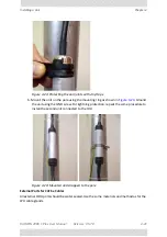
Page 50: ...the CAT 5e cable Start at Start Point at the bottom of the cable gland as shown in Figure 4 22 Finish at End Point of the CAT 5e cable 2 5cm after the end of the shrink tubing Stretch the tape and ap...

Page 51: ...ng the mounting ring as shown in Figure 4 24 Ground the unit using the GND screw For lightning protection repeat the same procedure to install the second unit connected to the IDU Figure 4 24 Mounted...

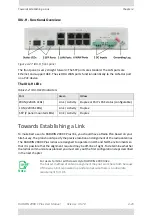
Page 52: ...4 6 Connecting the ODU to an IDU H Connect the IDU port to any of the six PoE ports of the IDU H Connecting the IDU H device to a network The IDU H has two LAN ports either of which may be used for ne...

Page 53: ...f the radio antennas The RADWIN 2000 C Plus radios are designed to operate in nLOS and NLOS environments so that it is possible that the alignment required may be off line of sight To determine whethe...

Page 54: ...ents common to all systems are Hard disk 1 GB free space Network 10 100BaseT NIC Graphics 1024x768 screen resolution with 16 bit color Any modern Web browser to view additional material use the Web In...

Page 55: ...to start browse to your CD DVD drive chose the setup exe program and run it Getting Started with the RADWIN Manager Preparation for First Log on To start the RADWIN Manager 1 Connect the managing comp...

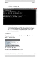
Page 56: ...Check your Ethernet connection and that both the PoE and ODU are switched on and then try again If you do not succeed seek assistance from RADWIN Customer Service 4 Dismiss the command line session Fi...

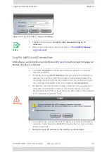
Page 57: ...tached ODU If you log on using Local Connection but your physical connection is not local i e anything other than a direct connection between the managing computer and the PoE device then any configur...

Page 58: ...under SNMPv1 and SNMPv3 In what follows below we assume that SNMPv1 is in use In Table 5 2 at end of the section we show the difference between SNMPv1 and SNMPv3 at log on time The RADWIN Manager pro...

Page 59: ...latter function has legal ramifications requiring familiarity with local regulations You may choose the SNMP version If your firewall blocks SNMPv3 messages and for security reasons cannot be changed...

Page 60: ...ct to an unsupported device on an otherwise valid IP address for example a LAN printer will result in the following error message Table 5 2 User types default passwords and function User Type Default...

Page 61: ...the sector is unreachable the following error message will be displayed Figure 5 7 Unreachable device message Incorrect Password If you type an incorrect password in the Login window the follwing mess...

Page 62: ...key which functions as a temporary master Community String Copy paste the supplied alternative key to both the Read Only and Read Write fields in the log on window Figure 5 4 This gets you to the RAD...

Page 63: ...gy As supplied both ODUs are factory pre configured as HSUs One of them typically the one to which you logged on in the previous chapter must be defined as Link Master ODU The Link Master ODU requires...

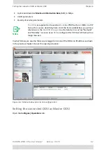
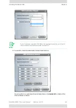
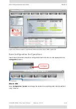
Page 64: ...n the previous chapter Here is the opening situation Figure 6 1 Main window prior to link configuration Setting the connected ODU as Master ODU Open the Configure Operations tab Note The ODUs as suppl...

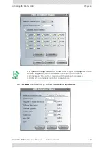
Page 65: ...indow enables you to switch between HSU mode Link Slave ODU and HBS mode Link Master ODU Click the HBS button At the confirmation popup window click OK to continue A further confirmation is displayed...

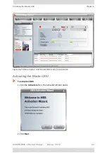
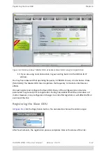
Page 66: ...l Release 3 5 70 6 4 Activating the Master ODU Chapter 6 Figure 6 2 Main window Link Master ODU ready for Activation Activating the Master ODU To activate a HBS 1 Click the Activate button The Activat...

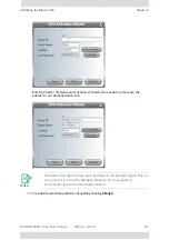
Page 67: ...All fields are mandatory Here are the entries for our demonstration link 3 The Link Password may also be changed by clicking Change Note The Sector ID is split into two parts as shown in the previous...

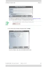
Page 68: ...ing the Link Password may be found in Changing the Link Pass word It is best left as is if there is no pressing need to change it 4 From the previous Activation Wizard window click Next Enter the IP d...

Page 69: ...e Master ODU Chapter 6 To continue click Next 5 The next window is used to set the frequency and channels The default frequency is the lowest available 5 735 GHz in the operating band 5 730 5 845 GHz...

Page 70: ...6 7 For our purposes we choose 5 820 GHz right hand selector wheel Observe that the right hand spin wheel is no longer displayed Had you left Other enabled you could have chosen a frequency by working...

Page 71: ...6 9 To use ACS check the Automatic Channel Selection box You can perform a customized channel selection or click Select All to check all the channel boxes as shown Note If your hardware supports 250...

Page 72: ...The Antenna type and Tx Power window is presented Note For operation using Licensed 3 X bands under FCC part 90 subpart Z and IC RSS 197 supporting 3 650 3 700 GHz The Master ODU does not commence any...

Page 73: ...und information about setting antenna parameters in Setting Antenna Parameters Choose your Antenna Type Required Tx Power Antenna Gain and Cable Loss We will set Required Tx Power to 5 dBm for our exa...

Page 74: ...ster ODU tries to optimize the frequency to minimize interference effects We next register and configure the Slave ODU Many of the configuration and service parameters may be set prior to registration...

Page 75: ...window Link Master ODU activated Slave ODU registered Basic Configuration for Operations Several basic parameters should be configured for both link sites Use the appropriate site Configuration butto...

Page 76: ...uration of the Slave ODU 1 Go to Configuration System and change the Name Contact and Location fields to meaningful values 2 In the Tx Antenna tab ensure that Tx Power is set appropriately For our dem...

Page 77: ...3 5 70 6 15 Basic Configuration for Operations Chapter 6 4 Click OK on the Configuration window to save your changes You are asked to confirm 5 Accept the changes Here is the status of the Link Figure...

Page 78: ...s Menu Item Purpose Reference Services Configuration MIMO Modes Transmission Ratio Maximum Information Rate VLAN Functionality with RADWIN 2000 C Plus Quality of Service Tools Spectrum View Changing t...

Page 79: ...nk Events Log The Events Log records system failures loss of synchronization loss of signal compatibility problems and other fault conditions and events Get Diagnostics Retrieving Link Information Run...

Page 80: ...about internal traps and alarms see Chapter 9 The events are displayed in the Events Log in the lower right hand panel of the RADWIN Manager main window Figure 6 9 Events Log panel The events log pro...

Page 81: ...tware Upgrade required Gray Slave ODU unregistered Table 6 2 Status Line Items Item Description Connection State Available or Unreachable depending on sync status Connection Mode Network Over the Air...

Page 82: ...1 Link site window fully configured link Here are the site tool bars in greater detail Figure 6 12 Site Tool Bars Table 6 3 Site Buttons Description Menu Button Applies to site Purpose Reference Both...

Page 83: ...site level configuration is covered in Site Configuration MIMO Modes If you are using Dual Antennas you may check a MIMO Mode Spatial Multiplexing default splits the data in to two streams on transmis...

Page 84: ...details about configuring and using HSS see Chapter 10 If the Master ODU is an HSS master you will see something like this Figure 6 14 HBS Collocated master Moving the slider to the right in stages y...

Page 85: ...ottle leaving the uplink or downlink as Unlimited commits the link to operating at best effort Changing the Link Band Changing the Band in use is always carried out at the link level not per installed...

Page 86: ...Release 3 5 70 6 24 Changing the Link Band Chapter 6 Figure 6 15 Change or Add Bands 2 Select the required Band and click OK For our purposes we choose 5 720 5 960 GHz Universal The band is highlight...

Page 87: ...RADWIN 2000 C Plus User Manual Release 3 5 70 6 25 Changing the Link Band Chapter 6 Figure 6 16 Add Change Band dialog 3 Click the right button The following window opens...

Page 88: ...the working channel bandwidth and channel selection as in the activation process Click OK to accept your choice You are returned to the display in Figure 6 16 5 Click OK again The following cautionar...

Page 89: ...n You may also add new Bands by clicking the Add Bands button There are several provisos to this Additional Bands must be available for your hardware Such additional Bands must be available within the...

Page 90: ...e Link Band Chapter 6 Figure 6 17 Add Bands Instructions Panel The serial numbers displayed are those of the ODUs in the link Click Copy to Clip board 2 Now carry out steps 2 to 5 in Figure 6 17 Step...

Page 91: ...ual Release 3 5 70 6 29 Changing the Link Band Chapter 6 3 Fill out the requested details Remember to terminate the dialog by clicking the Get Key button 4 The results of your request will be displaye...

Page 92: ...The next time you enter the Change Bands tab the new bands will be available Configuring AES 256 Encryption Support AES 256 support is enabled from the Master ODU To enable AES 256 Encryption support...

Page 93: ...le you saved in the previous step 6 Click Activate Yo can confirm activation by opening the Security tab The AES 265 check box previously grayed out is now available Check it to commence AES 256 Encry...

Page 94: ...DU Over the Air You can log on to the Slave ODU The log on procedure is the same as for the Master ODU The main window will appear as in Figure 6 5 but with the Master ODU and Slave ODU units reversed...

Page 95: ...le bar has three buttons on the right hand side Figure 6 21 Add Remove site buttons The left button opens up a Windows file dialog to locate a list of locations to backup The list has the following fo...

Page 96: ...guration produces a text file in the format of the above example for backing up an installed link The files produced by the above process are 10 104 4 4_26 02 2014 backup 10 104 4 2_26 02 2014 backup...

Page 97: ...he Monitor file contains a vast amount of information and can become inordinately large very quickly You should therefore choose a longer sampling interval if you intend to store this information for...

Page 98: ...re again per ODU To avoid over writing you should use file names reflecting their source ODU The SNMPv3 User and Password are relevant if you are using SNMPv3 In this case trap messages are keyed to t...

Page 99: ...assword You may change your log on password here from the default admin Restore Alerts Many alert messages in the RADWIN Manager have an option of the form Do not show this message again These alert m...

Page 100: ...ster ODU A Telnet terminal can be used to configure and monitor the RADWIN 2000 C Plus To start a Telnet session on the Master ODU use telnet ODU_IP For example if you run Telnet as follows telnet 10...

Page 101: ...y bands Displays available bands Table 6 6 Master ODU Telnet Set Immediate Commands Command Explanation set ip ipaddr subnetMask gateway Set the ODU IP address subnet mask and gateway The user must re...

Page 102: ...mmand will reset the ODU A new Telnet session to the ODU may be opened after the reset is complete help Displays the available commands Table 6 7 Master ODU Telnet Set Commands requiring Reset Command...

Page 103: ...about the HSU display ethernet Displays Port table State Status and action display ethernet_errors Displays Cable statistics display ntp Displays Time Server and Offset display PM interface AIR LAN1 i...

Page 104: ...eply set name new name Set the name of the link set location new location Set the name of the location set contact new contact Set the name of the site manager set ethernet port LAN1 mode AUTO 10H 10F...

Page 105: ...Figure 7 1 Site Tool Bars Table 7 1 Site Buttons Description Menu Button Applies to site Purpose Reference Both Open the Site Configuration Window Both Recent Events Both Active Alarms HBS Deactivate...

Page 106: ...onfiguration window in detail noting differences between the HBS and HSU side of Link site window We also comment briefly on the last four items in Table 7 1 Site Configuration Window The Site Configu...

Page 107: ...Chapter 7 Figure 7 3 Site Configuration window Slave ODU HSU The tool bars and tabs common to both sites have identical functionality Configuration Tabs System We used this tab in during the link con...

Page 108: ...ameters are automatically inherited by the Slave ODU when you use OK or Apply The Advanced button enables to choose a throughput mode Throughput Mode determines how the Adaptive Modulation mechanism w...

Page 109: ...during activation Whatever the case you may use this tab at either site for further fine tuning Changing the numerical antenna parameters in this way will take immediate effect without service interru...

Page 110: ...S check the Enabled check box Ensure that the correct Operational state is selected in our example Hub Site Client Continue Tx Click Apply or OK to enable HSS See Chapter 10 for further detail about H...

Page 111: ...is displayed 2 Enter the Trap Destination IP Address and Port It could be the IP address of the managing computer The events log will be stored at the addresses chosen 3 For Security model you may cho...

Page 112: ...identally locking yourself out of the link To enable VLAN for management 1 In the window of Figure 7 4 check the Enabled box 2 Enter a VLAN ID Its value should be between 2 and 4094 After entering the...

Page 113: ...in Figure 7 5 Figure 7 5 Supported protocols SNMP support is permanently enabled You may choose between SNMPv1 SNMPv3 or both If you choose SNMPv3 you will be offered the following cautionary message...

Page 114: ...Service should you require assistance Security Figure 7 6 Sector Security settings Master ODU The Security dialog enables you to change the Link Password and the SNMP Community strings If you have AES...

Page 115: ...he Security tab Figure 7 6 The Change Link Password dialog box opens Figure 7 7 Change Link Password dialog box 2 Enter the current link password The default link password for a new ODU is wireless p2...

Page 116: ...o manage the ODU if the read write or the read Community values are forgotten A new Community value may be obtained from RADWIN Customer Service for the purpose of setting new Community You must also...

Page 117: ...sswords Forgotten SNMPv1 Community String If the read write Community string is unknown an alternative Community key can be used The alternative Community key is unique per ODU and can be used only to...

Page 118: ...he offset from the Universal Coordinated Time UTC If there is no server available you can either set the date and time or you can set it to use the date and time from the managing computer Note that m...

Page 119: ...ering an IP address for the NTP Server click Clear and then enter the new address 4 Set your site Offset value in minutes ahead or behind GMT1 5 To manually set the date and time click Change and edit...

Page 120: ...ts Configuration The ODU Ethernet port mode is configurable for line speed 10 100 1000BaseT and duplex mode half or full duplex Line speed 1000BaseT is only available if the ODU is connected to A GbE...

Page 121: ...e Operations Figure 7 14 Restore Factory Settings License Activation and Change ODU Mode Reverting to Factory Settings Clicking the Restore Defaults button opens the following self explanatory dialog...

Page 122: ...stances it may involve purchasing the relevant license from RADWIN You should contact Customer Service for details The currently available enhancements are shown in Appendix 7 below Change ODU Mode We...

Page 123: ...click Apply or OK Deactivate Master ODU Deactivating the Master ODU halts traffic over the link and drops it back to the default transmission mode prior to configuration with one exception The Slave...

Page 124: ...ave ODU Chapter 7 Suspend a Deregistered Slave ODU You may break the link cause a full sync loss to the deregistered Slave ODU for a fixed amount of time Reset Master ODU Reset Slave ODU The reset fun...

Page 125: ...pe of this manual A variety of publications on the subject are available from the relevant FCC Web site http wireless fcc gov services index htm job service_home id 3650_3700 See also http hraunfoss f...

Page 126: ...ility and if still not available to transmit regardless Basically the idea is this Suppose that the Master ODU is set to Sharing Percentage of say 20 and Minimum Contention Slot length of 10 ms as sho...

Page 127: ...Help Where to obtain support Retrieving Link Information The Get Diagnostics feature collects and writes link and Manager information from selected sites into a text file The file information can be u...

Page 128: ...the information On completion the status of the checked items is confirmed Link Information Information about the HBS and HSU settings Site Configuration Data about the site parameters Monitor Detaile...

Page 129: ...Throughput from the Tools tab Note The Spectrum Analysis output is available directly from the Spectrum View utility as a CSV file see Spectrum View The format in the Diagnostics report is intended f...

Page 130: ...imated throughput is displayed At the end of 30 seconds the display reverts to normal Recent Events The Recent Events log records system failures loss of synchronization loss of signal compatibility p...

Page 131: ...ext file The Events Log includes the following fields Sequential number ID Date and time stamp Message Trap source IP address of the ODU that initiated alarm You may filter the events shown by choosin...

Page 132: ...and collects statistics data for the air interface and Ethernet ports It does so continuously even when the RADWIN Manager is not connected The report is obtained from the Tools tab The on screen and...

Page 133: ...Threshold button enables you to set the upper traffic thresholds for reporting Traffic conditions above the threshold indicate congestion and probably lost frames The thresholds are set separately fo...

Page 134: ...re recorded every 15 minutes the last 30 days of recordings are maintained Roll over is at midnight UAS Unavailable Seconds Seconds in which the interface was out of service ES Errored seconds The num...

Page 135: ...es of 5dB and 8dB from the current RSS are typical TSL Threshold A counter is maintained of the number of second intervals during which Tx power exceeds this threshold BBER Threshold The Background Bl...

Page 136: ...s not finished due to connection issues Warning Factory setting failed due to connectivity problem to ODU Reset The process was not finished due to connection issues Warning Factory setting failed due...

Page 137: ...r release Wizards are not available RADWIN Manager will be used just for monitoring Upgrade the RADWIN Manager You will get this message as a pop up The Manager identified a newer ODU release at the l...

Page 138: ...ge including antenna size cable loss and climate conditions For full details see Chapter 18 To run the Link Budget Calculator from the Windows Start Menu Go to Start Programs RADWIN Manager Link Budge...

Page 139: ...Part 2 Site Synchronization Release 3 5 70...

Page 140: ...HSS method uses a cable connected from the Master ODU to all collocated ODUs this cable carries pulses sent to each ODU which synchronize their transmission with each other The pulse synchronization e...

Page 141: ...te Synchronization 1 Figure 10 3 Collocated units using Hub Site Synchronization 2 The units are connected to each other with HSS cables and HSS Distribution Units One of the radios in the site is def...

Page 142: ...ports up to ten collocated ODUs In addition to each unit being connected to its PoE device the collocated unit has an additional cable that is connected to the HSS Unit The HSS Unit is a compact weath...

Page 143: ...g a Single HSS Unit Figure 10 5 HSS Wiring schematic The wiring as shown in Figure 10 5 is self explanatory The Sync signal path is less self evident If we set ODU 1 on SYNC 1 to HSS Master then the S...

Page 144: ...o nine ODUs may be connected to the first HSS unit using HSS ports SYNC 1 SYNC 2 SYNC 3 up to SYNC 9 in order without leaving empty ports 2 The next available SYNC port of the first HSS unit should be...

Page 145: ...s are populated in ascending order from SYNC 2 Condition 2 Total HSS Cable Length The total path of the HSS sync pulse must not exceed 300m This applies no matter how many HSS units are used To illust...

Page 146: ...nsparently chooses the optimal RFP RFP and HSS When HSS is used the RFP for the collocated radios must be selected manually RADWIN 5000 radios use the Time Division Duplex TDD mechanism Under HSS TDD...

Page 147: ...the RFP that gives you the Best Fit or Available for required system services and select the channel bandwidth accordingly Table 10 2 Radio Frame Pattern Table RADWIN 2000 C Plus RADWIN 5000 RFP 5 10...

Page 148: ...must use RFP E RFP influences capacity and latency Using the Link Budget Calculator you can see the effect of the RFP on the Ethernet throughput link Configuration and HSS The Hub Site Synchronizatio...

Page 149: ...eaning Color code Generating ODU is HSM and generates the sync pulse Green Detected ODU is HSC and detects the sync pulse Not detected ODU is independent Generating and detected HSM but other HSM pres...

Page 150: ...rom the GPS once per second It distributes a RADWIN proprietary synchronization signal to all other ODUs using the RS422 protocol and the standard HSS mechanism where the GSU acts as an HSM unit When...

Page 151: ...communicating as shown in Figure 11 2 Consider GSU 1 and GSU 2 Both collocated towers transmit and receive simultaneously However the radios communicating at GSU 1 and GSU 2 must transmit and receive...

Page 152: ...Phase and odd ordered links GSU 1 and GSU 3 above must be unshifted Normal Phase The phase shift is half of the Radio Frame Duration RFD from the chosen RFP The scheme is shown in Figure 11 3 Since th...

Page 153: ...from its GPS then it moves to self generation HSM mode like an ordinary HSM ODU until its GPS recovers Figure 11 4 Make the GSUs the first two collocated units Redundancy switching is completely tran...

Page 154: ...20 In the example screen captures below we use 10 104 20 1 with Subnet Mask 255 255 0 0 and Gateway 10 104 10 21 Mounting the GSU Mount the GSU and antenna Ensure that its ODU port connected to its Po...

Page 155: ...in widow at startup The top five items in the GSU Monitor panel are taken from a satellite The transmission Phase may be Normal as shown or Shifted It purpose together with the Tx Ratio bar will be ex...

Page 156: ...ere are no Installation or Configuration wizards Such configuration as is necessary is carried out using a modified version of the standard Site Configuration Similarly the Tool bar is a subset of tha...

Page 157: ...tion tool Figure 11 8 Site Configuration GPS Sync Unit 1 Setting the RFP for HSS The GSU is automatically configured as HSS Master HSM If the hub site consists only of WinLink 1000 units then any suit...

Page 158: ...me RFP transmit one half a RFD apart see Figure 11 3 above 2 Setting the Tx Transmission Ratio Since the GSU is always HSM it must be able to cater for hub site RADWIN 2000 C and later based links See...

Page 159: ...Configuring the GSU Chapter 11 Site Configuration Management Figure 11 9 Site Configuration Management Here you set the GSU IP address subnet mask and gateway You also set trap addresses here It is i...

Page 160: ...Plus User Manual Release 3 5 70 11 11 Configuring the GSU Chapter 11 Site Configuration Inventory Figure 11 10 Site Configuration Inventory Site Configuration Security You can only change the SNMP Com...

Page 161: ...3 5 70 11 12 Configuring the GSU Chapter 11 Figure 11 11 Site Configuration Security Site Configuration Date and Time ODU Recent events alarms and traps are time stamped from the time method chosen h...

Page 162: ...Plus User Manual Release 3 5 70 11 13 Configuring the GSU Chapter 11 Figure 11 12 Setting the date and time for trap reporting Site Configuration Operations The only available action here is Restore S...

Page 163: ...RADWIN 2000 C Plus User Manual Release 3 5 70 11 14 Configuring the GSU Chapter 11 Figure 11 13 Site Configuration Operations...

Page 164: ...d diagnostic reports are similar to those of WinLink 1000 GSU Telnet Support To configure the GSU with Telnet start a Telnet session using telnet GSU_ipaddr For example if you run Telnet as follows te...

Page 165: ...in 10 104 20 1 display gpsinfo Current GPS time 102941 000 Current GPS latitude 51 500000 Current GPS N S Indicator N Current GPS longitude 0 000000 Current GPS E W Indicator E Current GPS number of s...

Page 166: ...Part 3 Advanced Installation Topics Release 3 5 70...

Page 167: ...RADWIN 2000 C Plus User Manual Release 3 5 70 12 1 Chapter 12 Reserved...

Page 168: ...gy is retained Recall that HBS always means the Master ODU and HSU always means the Slave ODU VLAN Background Information on the Web The standards defining VLAN Tagging are IEEE_802 1Q and extensions...

Page 169: ...VLAN ID and EtherType 0x9100 to all frames as configured by the service provider Provider VLAN ID The system always adds to each frame tags with VLAN ID and EtherType 0x9100 Therefore For a frame wit...

Page 170: ...onfigured by the user Frames which are already tagged at ingress are not modified and pass through a Priority Code Point PCP which refers to the IEEE 802 1p priority It indicates the frame priority le...

Page 171: ...s configured for management traffic separation by VLAN and as Provider port then the received management frames must be double tagged as follows Table 13 2 Port settings Egress direction Transparent T...

Page 172: ...agement and data ports Define only a data port with Provider function Configuration of VLAN Tagging for Ethernet Service To set up an HSU for VLAN tagging 1 Open Services Configuration and then click...

Page 173: ...shown 4 Click OK to accept 5 For user VLAN tagging click the Tag Radio button In Tag mode Ethernet frames are tagged or untagged to distinguish between differ ent networks 6 For completely transparen...

Page 174: ...t Frames are not modified and are forwarded transparently All frames with VLAN tag are untagged Allow VLAN IDs Allow up to 4 VIDs to be passed through Untag VLAN IDs Untag the VLAN tag of the selected...

Page 175: ...hat is False Radar Mitigation False Radar Mitigation capability is an advanced method to reduce or eliminate false radar detection and DFS triggering False positives False radar detection can be cause...

Page 176: ...riable pulse width having variable repetition frequency Staggered False radars with variable repetition frequency within a burst period Applies to 5 4 GHz ETSI only Configuring False Radar Mitigation...

Page 177: ...r detection without completely blocking out real radar detection 4 Check the mitigation features to be used 5 When you are satisfied with your configuration parameters click OK to save them and dismis...

Page 178: ...latitude and longitude 2 Use the TDWR Location Information table to determine if the distance between the device and any TDWR tower is less than 35 km 3 If the distance is less than 35 km then regist...

Page 179: ...RADWIN 2000 C Plus User Manual Release 3 5 70 15 2 Registering the Device Chapter 15 2 Click the User Registration button to enter the registration page...

Page 180: ...IN 2000 C Plus User Manual Release 3 5 70 15 3 Registering the Device Chapter 15 3 Fill in the registration page and click Register 4 To complete device registration enter the Register Device tab as s...

Page 181: ...DWIN 2000 C Plus User Manual Release 3 5 70 15 4 Registering the Device Chapter 15 You are offered this 5 Fill in the required information in the preceding web page and click the Register Device butto...

Page 182: ...ATLANTA W 084 15 44 N 33 38 48 5615 MHz 962 113 IL MCCOOK W 087 51 31 N 41 47 50 5615 MHz 646 97 IL CRESTWOOD W 087 43 47 N 41 39 05 5645 MHz 663 113 IN INDIANAPOLIS W 086 26 08 N 39 38 14 5605 MHz 7...

Page 183: ...4 PA HANOVER W 080 29 10 N 40 30 05 5615 MHz 1266 113 PR SAN JUAN W 066 10 46 N 18 28 26 5610 MHz 59 113 TN NASHVILLE W 086 39 42 N 35 58 47 5605 MHz 722 97 TX HOUSTON INTERCONTL W 095 34 01 N 30 03 5...

Page 184: ...QoS is a technique for prioritization of network traffic packets during congestion RADWIN 2000 C Plus links support two classification criteria VLAN based or Diffserv based You may choose which of the...

Page 185: ...across the four Quality queues The default weights as percentages are shown in Table 16 1 Setting up the Link for QoS Preparing for QoS Open Services Configuration and then click the QoS Configuration...

Page 186: ...ettings for Diffserv and VLAN are as shown in the next two figures If you un check a queue it will be disabled for the link It will not prevent the HSU from configuring it as live The purpose behind t...

Page 187: ...ht you will receive an error message You will be required to correct this before leaving the window other than by cancel lation If you are under booked for example by setting a queue to zero the unuse...

Page 188: ...RADWIN 2000 C Plus User Manual Release 3 5 70 17 1 Chapter 17 Reserved...

Page 189: ...Part 4 Field Installation Topics Release 3 5 70...

Page 190: ...arameters have a default value that cannot be changed Band which determines frequency and regulation ODU series used Channel Bandwidth Tx Power maximum Tx power per modulation is validated Antenna Typ...

Page 191: ...which this relationship is true In a link with adaptive rate this will be the actual behavior MaxRange for a given air rate is the largest range for which Service The Ethernet and configured TDM trun...

Page 192: ...antennas setting which gives simplifying to The boresight clearance height is calculated as where About the Fresnel Zone The Fresnel zone pronounced frA nel with a silent s is an elliptically shaped...

Page 193: ...of the first Fresnel zone is defined as the combined path length of all paths which are half wavelength 1 2 of the frequency transmitted longer than the direct path If the total path distance is one w...

Page 194: ...dget Calculator The Link Budget Calculator for RADWIN 2000 C Plus is available at http www radwin com planner Go to the URL Your browser displays the following page shown partially Figure 18 2 Link Bu...

Page 195: ...2000 C Plus User Manual Release 3 5 70 18 6 Running the Link Budget Calculator Chapter 18 Figure 18 3 RADWIN 2000 C Plus LBC main window 2 Chose the required band Scroll down to get to Connectorized...

Page 196: ...CC IC Connectorized 3 Choose the Series 4 Choose the channel Bandwidth 5 Choose the required Tx Power Under Adaptive Rate this will be the Max Tx Power and you cannot change it 6 Choose the required a...

Page 197: ...tts 8 The Rate item may be used for calculating the Link Budget under best and worst scenarios It is always set to maximum under Adaptive Rate 9 If the required range between the two link sites is kno...

Page 198: ...nge will be calculated and displayed 10 Located to the right of the green Coordinates button is a drop down list of Climactic C Factor values It is only available if you choose a non adaptive rate Fig...

Page 199: ...7 Climactic C Factor description In Figure 18 8 we display a map of the world showing C Factor contours Figure 18 8 World map showing C Factor contours 11 Click Calculate to obtain the required perfor...

Page 200: ...ODUs are optimally aligned Services Type Ethernet only Ethernet Rate maximum throughput available for the chosen parameter combination Antenna height for LOS the minimum antenna height required for l...

Page 201: ...ned to show accurate information accommodating variations in frequency temperature and interference power and at the same time overcoming anomalies that tend to occur in high interference environments...

Page 202: ...ifferent spectral range and operating Band from the Master In the former case expect a noise hump around the channels used by the link due to the duty signals from the Master Where is the Spectrum Vie...

Page 203: ...lysis range is limited from 4900 to 6050 MHz with a maximum difference of 500MHz Erroneous entries will be shown with a red border like this The timeout is the maximum analysis time per site Use the b...

Page 204: ...two side arrows circled are used to reorder a stack of such view on the display area The remaining controls on the Spectrum View main window relate to Spectrum View data manipulation We will cover the...

Page 205: ...age Table 19 1 Spectrum View Analysis Display Buttons functionality Butto n Purpose Show Hide Antenna A Show Hide Antenna B Show Hide average Show Hide current channel HSUs only Show Hide maximum Show...

Page 206: ...of the main window Figure 19 1 Spectrum View Analysis color codes The green band reflects the current Master operating frequency Notice also the small fly over diskette icon circled to the upper left...

Page 207: ...r reverse and then click The swiped range is zoomed in You may repeat this several times The zoom applies to all charts for all element in the analysis An indicator is provided at the top right of eac...

Page 208: ...eds it The WI is a tool for technicians to quick install an ODU in a link with minimum effort It may also be employed by a user for a quick look at current operating parameters and the Recent Events l...

Page 209: ...DWIN 2000 C Plus RADWIN 2000 C and RADWIN 2000 B ODUs at release level 2 6 00 or later along with RADWIN 5000 ODUs from release 3 2 00 or later Software Your computer should have at least version 6 of...

Page 210: ...it the same way or by a direct connection logged on as Installer Look at Recent Events for either site You cannot Change default Tx Power Configure Spatial Multiplexing Diversity Manage other feature...

Page 211: ...d Password are respectively admin and netman as used for Telnet access You must click the Log In button to effect entry to the WI The foregoing applies to both ODUs The functionality described below i...

Page 212: ...window The link ID EBGX20560334 appears all or in part as the heading The main panel is self explanatory The green Active indicator will vary according to the status of the Master ODU shown by the RAD...

Page 213: ...l Bar Configure The Configure button opens the following display System The Name Contact and Location field may be changed Using Save commits them Clicking Refresh reverts the fields to their last Sav...

Page 214: ...RADWIN 2000 C Plus User Manual Release 3 5 70 20 7 The Tool Bar Chapter 20 You can use the Change Band button to open the following display The Antenna Tx Power button opens up the following window...

Page 215: ...The Tool Bar Chapter 20 The only item that can be changed is the Antenna Type Inventory The Inventory display is for information only Management The Management fields are all fully editable Caution Ch...

Page 216: ...RADWIN 2000 C Plus User Manual Release 3 5 70 20 9 The Tool Bar Chapter 20 If you change any of these fields you will cause an ODU reset...

Page 217: ...0 C Plus User Manual Release 3 5 70 20 10 The Tool Bar Chapter 20 Other You may change the ODU LAN port configuration You will receive the following notification This action of course has no bearing o...

Page 218: ...pter 20 Events The Recent Event List is displayed Reset Use this button to reset the ODU As usual for any action causing a sync loss you wil be asked to confirm the action Site Management Slave ODU Sl...

Page 219: ...Part 5 Product Reference Release 3 5 70...

Page 220: ...nge these specifications without notice ODU HBS and HSU Configuration Radio Architecture ODU Outdoor Unit with Integrated Antenna Connectorized for External Antenna or Embedded Uses RADWIN PoE type de...

Page 221: ...Q 802 1P QinQ TDD Intrasite Synchronization Supported using HSS TDD Inter Site Synchronization Supported through common GPS receiver per site Duplex Technology TDD Error Correction FEC k 1 2 2 3 3 4 5...

Page 222: ...0 2 407 2 467 10 2 402 2 472 20 2 392 2 482 40 2 4 ETSI 2 4095 2 4745 5 No ETSI EN 300 328 Supported CBW product dependent 2 407 2 477 10 2 402 2 482 20 2 392 2 492 40 3 4 ETSI 3 4105 3 4825 5 No ETSI...

Page 223: ...010 20 4 880 5 020 40 5 0 Universal 4 9975 5 1525 5 No N A 4 995 5 155 10 4 990 5 160 20 4 980 5 170 40 5 1 ETSI 5 150 5 350 10 Yes ETSI EN 301 893 v1 7 1 5 150 5 350 20 FCC 5 150 5 250 5 No FCC 47CFR...

Page 224: ...I 5 725 5 875 10 Yes ETSI EN 302 502 5 725 5 875 20 FCC IC 5 7275 5 8475 5 No FCC 47CFR Part 15 Subpart C and IC RSS 210 5 725 5 850 10 5 725 5 850 20 5 725 5 850 40 MII China 5 7375 5 8375 5 No MII C...

Page 225: ...20 17 250 3 470 3 610 3 480 3 600 23 3 590 3 710 3 600 3 700 25 Note The 3 480 GHz frequency is overlapped occurring in two di erent bands as shown If you wish to use the 3 480 GHz frequency you shoul...

Page 226: ...Power Consumption alone Master ODU 25W Slave ODU 20W TUV UL 60950 1 UL 60950 22 CAN CSA C22 2 60950 1 CAN CSA C22 2 60950 22 ETSI IEC EN IEC 60950 1 EN IEC 60950 22 FCC 47CFR Class B Part15 Subpart B...

Page 227: ...IEC CAN CSA Designed to meet 60950 1 60950 22 ETSI Designed to meet EN 300 386 EN 301 489 1 FCC Designed to meet 47CFR Part 15 Subpart B Class B CAN CSA Designed to meet ICES 003 Class B AS NZS Desig...

Page 228: ...2 CAN CSA C22 2 60950 1 CAN CSA C22 2 60950 22 ETSI EN IEC 60950 1 EN IEC 60950 22 FCC CFR47 Class B Part15 Subpart B ETSI EN 300 386 EN 301 489 1 EN 301 489 4 CAN CSA CEI IEC CISPR 22 04 Class B AS N...

Page 229: ...tions 200 A 10 700 s 500 operations DC Spark over 20 100 V s 150 V 100 V s 350 V 1000 V s 500 V Capacitance 2 pF DC Holdover Voltage 80V Enclosure Metal Connection to bonding Network Screw Dimensions...

Page 230: ...hed to the ODU unit or with an external antenna wired to the ODU via N type connectors All cables and connections must be connected correctly to reduce losses The required antenna impedance is 50 Conn...

Page 231: ...provides hermetic sealing The following table shows the connector pinout Table B 1 ODU PoE RJ 45 Connector Pinout Function Color PoE ODU Rx N White Green 1 1 Rx T Green 2 2 Tx T White Orange 3 3 Tx N...

Page 232: ...wer White Blue 5 5 TxRx D Power White Brown 7 7 TxRx D Power Brown 8 8 Table B 3 HBS HSS Unit Connection Pinout Color ODU RJ 45 HSS UNIT RJ 45 White Green 1 1 Green Not connected White Orange Orange 6...

Page 233: ...rface terminates in an 8 pin RJ 45 connector wired in accordance to Table B 4 DC Power Terminals DC PoE Table B 4 Fast Ethernet Connector Pinout Function Signal Pin Transmit Data positive TD 1 Transmi...

Page 234: ...es sections Private Controlled by RADWIN and supplements the public group This appendix describes the public and private MIB used by RADWIN Terminology The following terms are used in this appendix In...

Page 235: ...meters can break the air connection To correct air parameters inconsistency you must reconfigure each of the ODUs Common practice is to configure the remote site first and then to configure the local...

Page 236: ...the ODUs Integrated Antenna and Connectorized referred in the MIB as external antenna and GSU where applicable Figure C 2 Product MIB The GpsSynchronizerFamily MIB defines the GSU The general MIB incl...

Page 237: ...low the network layer in the protocol stack ifSpeed 1 3 6 1 2 1 2 2 1 5 Gauge RO An estimate of the interface s current bandwidth in bits per second For interfaces which do not vary in bandwidth or fo...

Page 238: ...ckets that higher level protocols requested be transmitted to a subnetwork unicast address including those that were discarded or not sent ifOutNUcastPkts 1 3 6 1 2 1 2 2 1 18 x Counter RO The total n...

Page 239: ...his parameter is reserved for the Manager application provided with the product winlink1000OduAdmHostsTable N A Trap destinations table Each trap destination is defined by an IP address and a UDP port...

Page 240: ...6 1 4 1 4458 1000 1 1 2 3 Integer RO This parameter indicates if the current Link Password is the default password winlink1000OduAdmConnectionTy pe 1 3 6 1 4 1 4458 1000 1 1 2 4 Integer RO This parame...

Page 241: ...gySu pported RO Ring Topology options are supported not supported winlink1000OduSrvRingVlanIdTable N A Ring VLAN IDs table winlink1000OduSrvRingVlanIdEntry N A VLAN ID of the internal ring messages Va...

Page 242: ...emaining Rate 1 3 6 1 4 1 4458 1000 1 3 1 Integer RO Current Ethernet bandwidth in bps winlink1000OduEthernetIfTable N A ODU Ethernet Interface table winlink1000OduEthernetIfEntry N A ODU Ethernet Int...

Page 243: ...d Transmit power in dBm This is a nominal value while the actual transmit power includes additional attenuation The min and max values are product specific A change is effective immediately winlink100...

Page 244: ...Valid values disabled 0 enabled 1 Rewriteable only in Point To Point products winlink1000OduAirChannelsAvail RO Channel state Product specific and cannot be changed by the user Automatic Channel Selec...

Page 245: ...nlink1000OduAirRatesEntry N A Air Rate indexes table entry INDEX winlink1000OduAirRatesIndex winlink1000OduAirRatesIndex RO Air Rate index winlink1000OduAirRatesAvail RO Air Rate availability dependin...

Page 246: ...3 6 1 4 1 4458 1000 1 5 4 0 7 1 5 Integer RO Represents the compatibility of TDM service under Channel BW of 10MHz in the specific Radio Frame Pattern winlink1000OduAirHssRfpEthChann elBW20MHz 1 3 6 1...

Page 247: ...main IP HSS Role Hss support Enabled HSS protocol Sync Status Location winlink1000OduAirHssMasterSlave Compatibility RO EHSM version compatibility Relevant to Ethernet HSS Clients only winlink1000OduA...

Page 248: ...uch stronger than Radio 1 RSS 1 Radio 2 RSS is stronger than Radio 1 RSS 0 Radio 2 RSS is equal to Radio 1 RSS 1 Radio 1 RSS is stronger than Radio 2 RSS 2 Radio 1 RSS is much stronger than Radio 2 RS...

Page 249: ...1 5 5 3 1 1 19 Integer RO Reflects the sub band DFS state winlink1000OduAirComboNumber OfSubBands 1 3 6 1 4 1 4458 1000 1 5 5 3 2 Integer RO Represents the number of Multi band sub bands winlink1000O...

Page 250: ...of a second since device up time If no CAC has performed on the channel the return value will be 0 winlink1000OduAirSpectrumChann elRadarDetected 1 3 6 1 4 1 4458 1000 1 5 5 6 5 1 13 Integer RO Was Ra...

Page 251: ...ed 2 Embedded_External 3 Embedded_Integrated 4 winlink1000OduAirAllowableChann elsStr 1 3 6 1 4 1 4458 1000 1 5 6 5 DisplayString RW A string representing the allowable channels Each character represe...

Page 252: ...nds 4 winlink1000OduPerfMonIntervalTa ble N A This table defines keeps the counters of the last day in resolution of 15 min intervals winlink1000OduPerfMonIntervalEn try N A This is an entry in the In...

Page 253: ...eived Level Reference starting from the present 15 minutes period winlink1000OduPerfMonAirCurrMa xRSL 1 3 6 1 4 1 4458 1000 1 6 4 1 2 Integer RO Current Max Received Level Reference starting from the...

Page 254: ...of seconds Receive Signal Level exceeded the RSL1 threshold per Day winlink1000OduPerfMonAirDayRSL Thresh2Exceed RO Number of seconds Receive Signal Level exceeded the RSL2 threshold per Day winlink1...

Page 255: ...RX Mega Bytes per day winlink1000OduPerfMonEthDayTx MBytes RO Current Transmit Mega Bytes per day winlink1000OduPerfMonEthDayEth CapacityThreshUnder RO The number of times throughput was below thresho...

Page 256: ...current traffic is above this threshold then corresponding counter is incremented winlink1000OduAgnGenAddTrapExt 1 3 6 1 4 1 4458 1000 1 7 1 1 Integer RW If yes is chosen the ifIndex Unit Severity Tim...

Page 257: ...tsTable winlink1000OduAgnLastEventsTable N A This table includes the last events When a trap is sent an event entry is added to the table winlink1000OduAgnLastEventsEntr y N A Entry containing the det...

Page 258: ...tPor tVIDs RW VLAN tag untag default VLAN ids for each port Right most digit is Vlan priority 0 6 other digits compose Vlan Id 1 4094 winlink1000IduAdmVlanLan1Untag gedVIDs RW VLAN untagged VIDs for L...

Page 259: ...N A IDU Possible Services table winlink1000IduSrvPossibleServices Entry N A IDU Services table entry INDEX winlink1000IduSrvPossibleServicesIndex winlink1000IduSrvPossibleServicesI ndex RO Table inde...

Page 260: ...DU Ethernet Interface table entry INDEX winlink1000IduEthernetIfIndex winlink1000IduEthernetIfIndex RO If Index corresponding to this Interface winlink1000IduEthernetIfAddress RO IDU MAC address winli...

Page 261: ...ffective immediately winlink1000IduTdmLineStatus RO Line status winlink1000IduTdmCurrentTable N A IDU TDM Links Statistics table winlink1000IduTdmCurrentEntry N A IDU TDM Links Statistics table entry...

Page 262: ...ed winlink1000IduTdmDesiredHotStan dbyMode RW Desired Hot Standby Mode winlink1000IduTdmHotStandbyOpe rationStatus RO The Link Actual Status winlink1000IduTdmBackupLinkConf iguration RW The current co...

Page 263: ...ate Index 1 3 6 1 4 1 4458 1000 3 1 6 2 1 11 Integer RW The rate index of both sides of the link to this HSU winlink1000HbsAirConfMacAddress 1 3 6 1 4 1 4458 1000 3 1 6 2 1 12 DisplayString RO HSU MAC...

Page 264: ...000HbsAirHsuOutFrames 1 3 6 1 4 1 4458 1000 3 1 7 2 1 18 Integer RO Number of bytes transmitted from the HSU Lan port winlink1000HbsAirHsuMacAddress 1 3 6 1 4 1 4458 1000 3 1 7 2 1 19 DisplayString RO...

Page 265: ...6 1 4 1 4458 1000 3 1 7 2 1 36 Integer RO Average data throughput Exported in Kbps transmitted in the DL towards the SU during the last second winlink1000HbsAirLinkUtilUpTraffic Kbps 1 3 6 1 4 1 4458...

Page 266: ...A Holds the bridge Vlan operations towards all the registered HSUs winlink1000HbsBridgeVlanEntry N A HBS bridge Vlan table entry INDEX winlink1000HbsBridgeVlanIndex winlink1000HbsBridgeVlanIndex RO HB...

Page 267: ...blEgre ssFilter4 1 3 6 1 4 1 4458 1000 3 3 2 1 1 10 Integer RW VLAN Filter4 VID winlink1000OduServiceVlanTblUnta gFilteredBitmap 1 3 6 1 4 1 4458 1000 3 3 2 1 1 11 Integer RW Represents in bitmap if t...

Page 268: ...3 4 1 1 7 Integer RW HBS performance monitor high traffic threshold winlink1000HbsPerfMonAirGenCur rTable N A This table defines keeps the ethernet counters of the current 15 min interval winlink1000...

Page 269: ...nt for point to point systems winlink1000HbsPerfMonAirGenDay HighTrafficThreshExceed RO The number of times actual traffic was above threshold each day winlink1000HbsPerfMonAirGenDay ActiveSeconds RO...

Page 270: ...58 1000 100 1 DisplayString RO Trap s Description Used for Trap parameters winlink1000GeneralTrapSeverity 1 3 6 1 4 1 4458 1000 100 2 Integer RO Trap s Severity Used for Trap parameters winlink1000Gen...

Page 271: ...The reason is s s Is the reason detectIDU 4 normal Indicates that the IDU was detected Raised by both sides of the link Contains a single parameter which is its description 1 Description IDU of Type...

Page 272: ...nd time configurationChanged 18 normal Indicates that the ODU recovered from an error but there are configuration changes Contains two parameters 1 Description Configuration changed Error code is n 2...

Page 273: ...e parameter which is its description 1 Description Failed to change the Link Password at on s s Is the Local Site name or Remote Site name or both sides of the Link externalAlarmInPort1Alarm 105 major...

Page 274: ...ch is its description 1 Description HSS multiple sync sources were detected hssSyncToProperSourceStoppedAlarm 119 major Indicates that synchronization to a proper sync pulse source was stopped Contain...

Page 275: ...gle parameter which is its description 1 Description LAN port status changed to disconnected poePortDisconnectedAlarm 140 major Indicates the POE port status changed to disconnected Contains a single...

Page 276: ...his Trap is sent every time an External Alarm Input fault of port 2 is cleared Contains a single parameter which is its description 1 Description External Alarm 2 User Text Alarm Cleared lanPort1Clear...

Page 277: ...enticationDisabled 224 normal Indicates that the Link Lock is disabled Contains a single parameter which is its description 1 Description Link Authentication has been disabled hotStandbyClear 225 norm...

Page 278: ...iption POE consumption within limits port is opened 2 s Is the Eth mode speed duplex incompatibleHbsHsu 246 normal Incompatible HBS HSU software versions no service mobilityLinkOff 247 normal Mobility...

Page 279: ...RADWIN 2000 C Plus User Manual Release 3 5 70 C 46 MIB Traps Chapter C A list of Trap Messages as displayed by the RADWIN Manager is shown in Manager Traps...

Page 280: ...i Min Safety Distance cm 5 8 Q3KRW5XMOD 5100A RW5XMOD 32 354 5 8 Q3KRW5XMOD 5100A RW5XMOD 29 251 5 8 Q3KRW5XMOD 5100A RW5XMOD 24 141 5 8 Q3KRW5XMOD 5100A RW5XMOD 16 60 5 8 Q3KRW5XMOD 5100A RW5XMOD All...

Page 281: ...C Plus User Manual Release 3 5 70 D 2 RF Exposure Chapter D Table D 2 Safety Distances for RADWIN 2000 C Plus ETSI Products Frequency Band GHz Antenna gain dBi Min Safety Distance cm 5 8 5 3 5 4 2 4 A...

Page 282: ...n and by automatic system decisions explained below Dual Antennas at the HBS and an HSU When using dual antennas at both sites single bipolar antenna or two mo unipolar antennas you can choose between...

Page 283: ...ly such a system can provide a robust link Antenna diversity requires antenna separation which is possible by using a dual polarization antenna or by two spatially separated antennas Use Diversity ins...

Page 284: ...ode Max Full Duplex Capacity Site A Site B 2 2 SM 50 Mbps Diversity 25 Mbps 2 1 25 Mbps 1 2 25 Mbps 1 1 25 Mbps Table E 2 RADWIN 2000 C Plus Air rates Antenna Modulation FEC Air Rate Mbps 20 MHz CBW 4...

Page 285: ...wer System shows the total transmission power of the ODU and is used to calculate the EIRP according to regulations Dual 64QAM 3 4 117 243 Dual 64QAM 5 6 130 270 Notes To see the relationship between...

Page 286: ...stem in accordance with the relevant regulation The precise relationship between the items in inequality is as follows Required Tx Power per radio will be adjusted down to the lesser of the value ente...

Page 287: ...ion une prise de courant avec une protection de terre En outre La cosse de masse sur l IDU C doit tre constamment connect e la protection de terre par un c ble de diam tre de 18 AWG ou plus Le mat rie...

Page 288: ...tions de s curit pendant le montage de ODU Avant de connecter un c ble l ODU la borne protectrice de masse visse de l ODU doit tre connect e un conducteur externe protecteur ou un pyl ne reli la terre...

Page 289: ...une grande clame voir Figure F 1 une petite clame voir Figure F 2 un bras voir Figure F 3 quatre visses hex t te M8x40 deux visses hex t te M8x70 quatre rondelles plates M8 trois rondelles lastiques M...

Page 290: ...RADWIN 2000 C Plus User Manual Release 3 5 70 F 4 Montage sur un pyl ne Chapter F Montage sur un pyl ne Figure F 4 Montage sur un pyl ne...

Page 291: ...RADWIN 2000 C Plus User Manual Release 3 5 70 F 5 Montage sur un mur Chapter F Montage sur un mur Figure F 5 Montage sur un mur...

Page 292: ...xation en m tal Pour installer une antenne externe sur un pyl ne 1 Attacher le support en U l arri re de l antenne en utilisant quatre rondelles plates quatre rondelles lastiques et quatre crous hex 2...

Page 293: ...7 12 configuration advanced 6 37 AES 256 encryption 6 30 basic 6 13 change oassword 6 37 changing the band 6 23 date time 7 14 Ethernet 7 16 events 6 36 GSU 11 6 Inventory 20 8 IP Addresses 7 6 Monito...

Page 294: ...ve to PoE Devices 4 22 functional overview 4 23 installing 4 22 status LEDs 4 23 Inventory configuration 20 8 WI 7 10 L LBC 9 12 availability 18 2 calculations 18 2 EIRP 18 2 Expected RSS and Fade Mar...

Page 295: ...eregistered Slave ODU 7 20 T Telnet 6 38 access to GSU 11 15 access to the Master ODU 6 38 access to the Slave ODU 6 41 thresholds 9 9 Throughput Checking 9 3 traps Manager 9 10 MIB C 38 U User Port C...

Page 296: ......
Page 297: ...Item Version Build Date UM 3 5 70 NMS 9 5 70 9536 20 03 2014 SWU Inventory 3 5 05 00 3515 00 20 03 2014 MIB 9 5 50 00 9520 09 01 2014 LBC 9390_Web 11 02 2014 Release type GA 30 03 2014...

Reviews: