


Service
Service Manual
6200
plus
Series
21
Fan Tray
Overview
The 6200
plus
provides a fan tray with three (3) 90 CFM cooling fans. The fan tray is
removable and can be serviced with minimal time and effort.
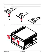
Fan Tray
The fan tray is housed in a compartment behind the front panel. The tray is held in place
within the chassis by rails on the card guide bracket. This creates a bulkhead between
the fan compartment and the passive backplane compartment.
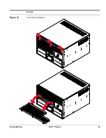
The procedure for installing the fan tray is outlined in the following table (
Figure 13
):
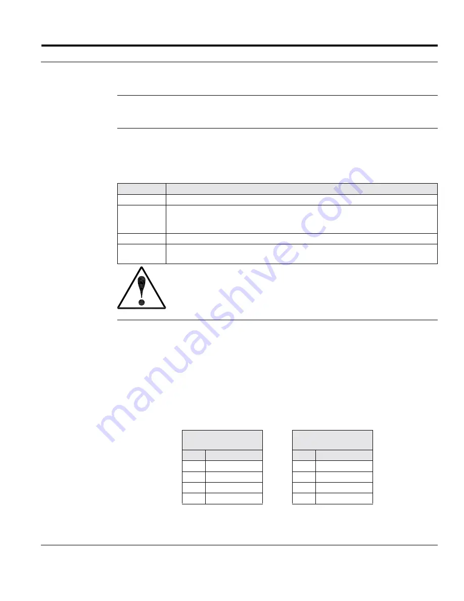
Fan
Connectors
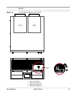
The fan tray contains an interconnect board that serves as a junction between the fans
and the power supply (
Figure 14
):
•
Fan Wires
: each fan has two wires, 12 volt DC and Ground. Wires for each fan
must be attached to the terminals on the interconnect board (
Figure 15
).
•
Power Supply
: the fan interconnect board has two (2) connectors for power supply.
One is the type typically used for hard disk drives, CD-ROM drives, etc. The other
is typically used for floppy disk drives. Either connector can be used.
Note:
Only one (1) connector from the power supply must be attached to the fan
interconnect board.
Step
Action
1
Position the fan tray over the fan compartment.
2
Attach the power cable to the fan tray connector board.
Note:
Access holes for the power cable are provided in the card guide bracket
and the fan tray.
3
Align the edges of the fan tray with the rails on the card guide bracket.
4
Lower the fan tray into the fan compartment.
Note:
The fan tray rests upon a ledge formed by the card guide bracket.
Always use caution when installing or removing the fan tray. Carefully move
the tray in or out of the chassis to avoid damaging the cables, fans, and other
equipment.
Hard Disk Drive
Type Connector
Floppy Disk Drive
Type Connector
Pin
Description
Pin
Description
1
+12 Volt DC
1
Not Connected
2
Ground
2
Not Connected
3
Not Connected
3
Ground
4
Not Connected
4
+12 Volt DC
Summary of Contents for 6200plus Series
Page 17: ...Service Service Manual 6200plus Series 9 Figure 4 Removing the Top Cover ...
Page 25: ...Service Service Manual 6200plus Series 17 Figure 10 Removing the Media Drawer ...
Page 27: ...Service Service Manual 6200plus Series 19 Figure 11 Removing the 3 Drive Bay ...
Page 28: ...Service 20 6200plus Series Service Manual Figure 12 Installing Drives ...
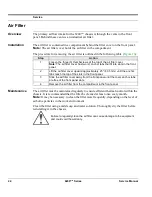
Page 33: ...Service Service Manual 6200plus Series 25 Figure 16 Air Filter Installation ...
Page 40: ...Service 32 6200plus Series Service Manual Notes ...


