65
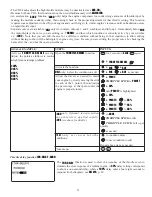
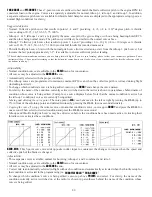
Adjustability:
•
Position
: -100% to +100%, with a default of -50% (off), +50% (on)
•
Channel:
Spoiler 1: ch8, or 3 (ch8 or 3*), Spoiler 2: NULL, or 3 (NULL or ch3*)
*
GLID (2A+2F)
mode
•
Elevator setting:
Rate: -100% to +100%, Delay: 0% to 100%
•
SWITCH A-H
fully assignable. Also
LOGIC SW
(
Lsw1 to 3
) may be assigned. Set up
LOGIC SW
: See p. 26.
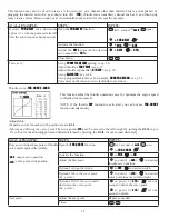
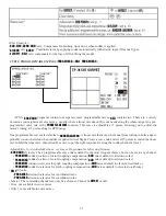
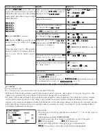
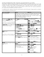
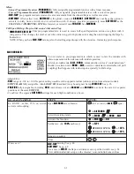
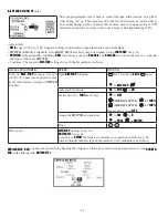
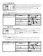
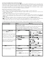
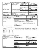
GOAL of EXAMPLE:
STEPS:
INPUTS:
2-servo spoiler mode.
Adjust the spoiler servo position to
60%
.
Open the
SPOILER MIX
function and
move to 2nd page.
for 1 second. (If
BASIC
,
again.)
C
to
SPOILER MIX
.
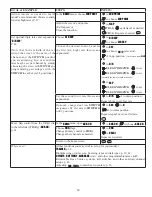
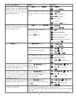
Activate the function.
C
to
MIX
.
to
ON
.
Assign the
SPO2-CH
. (Ex: CH3)
C
to
SPO2-CH
.
to
CH3
.
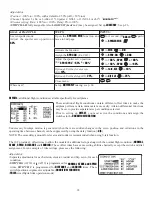
Adjust the spoiler servo position.
(Ex:
SPO1
SPO2
=
+55%
to
+60%
)
C
to
+50%
. (
SPO1
)
to
+60%
.
C
to
+50%
. (
SPO2
)
to
+60%
.
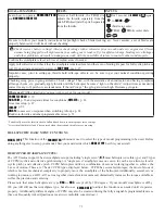
Optional: Set the elevator rate.
(EX:
10%
)
C
to
rate
-
ELE
.
to
10%
.
Optional: Set the delay. (EX:
25%
)
C
to
dly
-
ELE
.
to
25%
.
Close menu.
Where next?
Set up
BUTTERFLY
mixing: see p. 68.
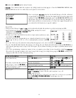
OFFSETs
DGGLWLRQDOÀLJKWFRQGLWLRQVDYDLODEOHVSHFL¿FDOO\IRUVDLOSODQHV
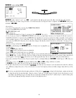
Unnecessary fusulage motion is generated when there are sudden changes in the servo position and variations in the
operating time between channels can be suppressed by using the delay function (
-dly-
).
NOTE: The same delay amount for elevator and rudder is recommended when using V-tail function.
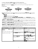
7KH&SURYLGHVRIIVHWWULPVWRDOORZWKHPRGHOHUDGGLWLRQDOVHWXSVDORQJZLWKWKHQRUPDOÀLJKWFRQGLWLRQ
NORMAL
,
START
,
SPEED
,
DISTANCE
and
LANDING
) These offset trims have same setting abilities basically except the switch and dial
assignment. For an example of trim settings, please see the following:
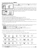
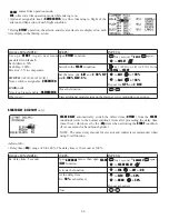
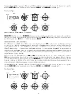
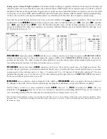
These additional flight conditions contain different offset trims to make the
saiplane perform certain maneuvers more easily. Aileron differential functions
may be set to provide separate rates per condition selected.
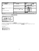
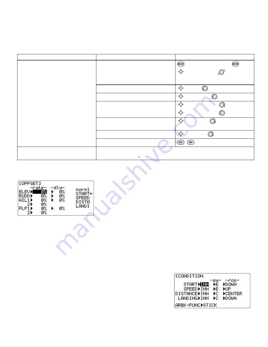
Prior to setting up
OFFSET
, you must active the conditions and assign the
switches in the
CONDITION/FUNCTION
.
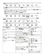
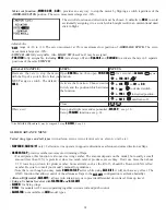
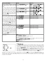
Adjustability:
6HSDUDWHDGMXVWPHQWVIRUHDFKDLOHURQHOHYDWRUUXGGHUDQGÀDSVHUYRIRUHDFK
condition.
•
SWITCH G
(
AT10
) or
E
(
AT10
) is programmed for
NORMAL
,
START, and SPEED
trims.
SWITCH C
is programmed for
DISTANCE
and
LANDING
trims. These
VZLWFKSRVLWLRQDVVLJQPHQWLVDGMXVWDEOH
CONDITION/FUNCTION
)
•
TRIM
item (Digital trim operation mode):

