background image


© 2015 Radiodetection Ltd 

32 

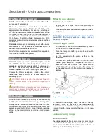
NOTE: It is not necessary to make a ground connection 
from the transmitter when using the clamp. 

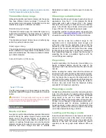
Transmitter clamp range 

Although transmitter and locator clamps look the same, 
they  have  different  internal  windings.  To  prevent  the 
wrong clamp being connected, transmitters and locator 
clamps have plugs of a different orientation. 

Standard signal clamps 

The  standard  clamps  apply  the  transmitter  signal  very 
selectively and effectively to a target cable up to 130mm 
(

5¼”)  in  diameter  using  frequencies  from  8kHz  to 

200kHz  

The  standard  and  small  clamps  have  a  double  spring 
action for positive toroidal contact. 

Small signal clamp 

The small signal clamp is useful for applying signals from 
8kHz to 200kHz to a target cable in a pedestal or other 
place with limited space. The clamp is suitable for cables 
up to 50mm diameter. 

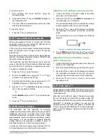
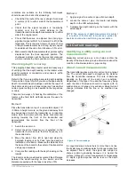
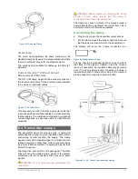
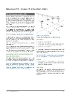
Current Direction (CD) clamp 


The CD clamp plugged into the accessory socket of the 
transmitter enables CD signals to be applied to individual 
cables. 

WARNING!. The transmitter must only be connected 

to live services using the appropriate accessory such as 
a plug connector or live cable connector. 

8.5 Sondes 

Sonde overview 

A sonde is a self-contained battery operated transmitter 
used  for  tracing  the  paths  of  pipes,  ducts,  sewers  and 
drains  and  in  the  precise  location  of  blockages  or 
collapses.  The  sonde  can  be  fitted  to  a  flexible  rod  for 
insertion or pushing through pipes  etc. and the smaller 
diameter sondes can be used in conjunction with jetting 
machines  and  blown  through  the  duct.  A  suitable 

Radiodetection  locator  can  then  be  used  to  locate  the 
sonde 

Choosing a suitable sonde 

Radiodetection offers a wide range of sonde to suit most 
applications:  From  the 

¼”  /  6  mm  diameter  S6  33kHz 

microsonde  which,  with  a  range  of 

6.6”  /  2m,  targets 

fiber-optic  micro  ducting  or  other  small  non-conductive 
pipes,  to  the  33kHz  Super  Sonde,  which  with  a  depth 
range of 50 feet / 15m targets deep sewer pipes. 

Consult  the  precision  locate  accessory  range  brochure 
or web page on 

www.radiodetection.com

 for a full list of 

all available sondes and their technical specifications. 


Check  that  the  sonde  has  sufficient  range  for  the 
application  and  is  dimensionally  small  enough  and 
sufficiently  robust  for  the  application.  Ensure  that  the 
frequency  of  the  sonde  corresponds  with  the  locator 
frequency;  the  locator  will  not  locate  the  sonde  unless 
the frequencies are the same. Sondes are marked with 
their  transmitting  frequency.  Ensure  that  the  means  of 
propelling  the  sonde  is  available  together  with  the 
correct fittings and couplings. 

Preparation 

Insert a new battery into the sonde. A new battery or a 
freshly  recharged  battery  should  be  used  at  the 
beginning of each day and preferably at the start of each 
new job. 

Before  inserting  the  sonde,  check  that  the  sonde  and 
locator are at the same frequency and working correctly. 
To do this, place the sonde on the ground at a distance 
from  the  locator  that  is  equal  to  the  rated  depth  of  the 
sonde. Point the locator at the sonde with the antenna in 
line with the sonde (the opposite of using the locator to 
locate  a  line)  and  check  that  the  bargraph  reading 
exceeds 50% at maximum sensitivity. 

Propelling a sonde 

Sondes have a thread at one end for connecting to drain 
rods, or to other devices for inserting and propelling the 
sonde  along  a  drain  or  duct.  Sondes  may  be  floated 
along  drains  at  the  end  of  a  tether  and  floats  are 
available for fitting to the sewer sonde and super sonde. 
Sondes can be strapped to high-pressure water jets or 
similar  devices  used  for  cleaning,  maintaining  and 
inspecting  drains.  Sondes  used  in  underground  drilling 
and boring operations are normally housed in the boring 
or drill head behind the boring or drill bit. 

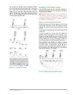
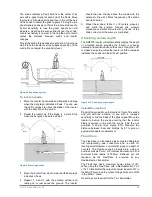
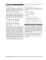
Locating and tracing a sonde 

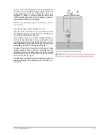
Insert the sonde in the drain or duct access and locate it 
while it is still just in view at the drain or duct entrance. 
Hold the locator vertical directly over the sonde with the 
antenna  in  line  with  the  sonde.  Adjust  the  locator 
sensitivity  so  the  bar  graph  reads  between  60%  and 
80%. 

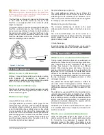
Figure 8.7: CD clamp 

Summary of Contents for RD8100

Page 1: ...RD8100 Precision Multifunction Cable Pipe Locator Operation manual 90 RD8100 OPMAN ENG 03...

Page 2: ...3 Current readings 26 Section 7 Locating techniques 28 7 1 Identifying target utilities 28 7 2 Signal ground connection 29 7 3 Double ended connections 29 Section 8 Using accessories 30 8 1 About acc...

Page 3: ...to live conductors is POTENTIALLY LETHAL Direct connections to live conductors should be attempted by fully qualified personnel only using the relevant products that allow connections to energized li...

Page 4: ...e equipment must accept any interference received including interference that may cause undesired operation This equipment has been tested and found to comply with the limits for a Class A digital dev...

Page 5: ...Manual outline Section 1 includes an overview of safety procedures and notices Review them before moving on to Section 2 and the rest of this manual Section 3 provides an overview of the RD8100 system...

Page 6: ...only the minimum level necessary to take your measurements Excessive exposure to loud sounds can cause hearing damage Do not attempt to open or dismantle any part of this equipment unless directed spe...

Page 7: ...15 Radiodetection Ltd 6 Figure 3 1 RD8100 Locator GPS active seeking satellite lock GPS satellite lock acquired 3 5 satellites fixed 6 8 satellites fixed 9 11 satellites fixed 12 or more satellites fi...

Page 8: ...con Displays the volume level 22 Current Direction arrows 23 Radio Mode Indicates when Radio Mode is active 24 Power Mode Indicates when Power Mode is active 25 Accessory indicator Indicates when an a...

Page 9: ...2015 Radiodetection Ltd 8 Figure 3 2 Tx Transmitter...

Page 10: ...mitter is in Induction Mode 18 A Frame Tx 5 B or Tx 10 B only Indicates when the transmitter is in Fault Find Mode 19 CD Mode indicator Tx 10 B only Indicates that the transmitter is in Current Direct...

Page 11: ...a modes with the exception of Peak FREQ Enable or disable individual frequencies ALERT Enable or disable StrikeAlert BATT Set battery type Alkaline NiMH or Li Ion ARROW Select NULL or proportional Gui...

Page 12: ...rtment Insert 2 good quality D cell batteries Note the polarity of the cells when inserting them in the battery tray Figure 4 2 Inserting locator batteries On the transmitter To fit the D cell batteri...

Page 13: ...battery pack If using the Li ion battery pack plug the lead into the battery connector fig 4 7 Figure 4 7 Connecting the Li Ion lead NOTE Fully charge your lithium ion battery pack before its first us...

Page 14: ...ut connector on the front of the battery pack Transmitter Li ion battery pack To recharge the battery pack remove the pack from the transmitter and connect the transmitter battery charger Figure 4 13...

Page 15: ...Select standby maximum standard power Table 4 2 Transmitter key actions NOTE to scroll through frequencies from high to low hold while pressing the button applies to both locators and transmitters 4...

Page 16: ...menu using the or arrows 3 Press the key on the locator or the key on the transmitter to enter the BATT menu 4 Scroll through the battery options using the the or keys 5 Press the key to accept your s...

Page 17: ...a flashing mode icon Both the depth and current measurements will be disabled in the event of an overload 4 7 TruDepth measurement All RD81 00 locators use TruDepth to measure depth automatically when...

Page 18: ...neral purpose locate frequency for the intended locate task by measuring the impedance of the target cable or pipe SideStepauto helps to improve locate accuracy by determining the best signal SideStep...

Page 19: ...rity It is also possible to measure potential voltage that may be present on utilities to warn of potentially dangerous or harmful voltages present In measure mode the measurement is derived from an A...

Page 20: ...paired device OFF Select this to switch off the internal GPS module and save battery SBAS Select this to switch ON or OFF SBAS Satellite Based Augmentation System SBAS can improve GPS accuracy particu...

Page 21: ...ON When using custom frequencies in the range of 692Hz to 704Hz or 981Hz to 993Hz the locator audio may interfere with the locator and must be turned off NOTE Some frequencies e g 440Hz may be reserve...

Page 22: ...cating Buried Pipes and Cables which is available as a free download from www radiodetection com To select a frequency on the locator 1 Press the key to cycle through available frequencies 2 Alternati...

Page 23: ...response is at its maximum level where the Null point is located then there is no or very limited distortion present In Peak mode the following indicators are displayed by the LCD Right and left arrow...

Page 24: ...tion of a target line after it has been traced and its position is approximately known Start with medium output power from the transmitter medium frequency on the transmitter and locator and Peak or P...

Page 25: ...ductive search procedure is a more certain technique for locating unknown lines This type of search requires a transmitter and locator and two people This type of search is referred to as a two person...

Page 26: ...to note that the RD8100 locator will only display depth and current in applicable modes when the locator is correctly orientated above the target line cable or sonde To ensure the locator is correctly...

Page 27: ...er 1 Switch the locator on 2 Select the same frequency as is selected on the transmitter but make sure that this frequency is in the sonde mode 3 Move the locator from left to right and when the bargr...

Page 28: ...ducts that allow connections to energized lines Signal current measurements Pinpoint the line and confirm the accuracy of the Peak pinpoint with null arrows Check the locator is directly over the line...

Page 29: ...r to marking the wrong line A certain degree of coupling is unavoidable in many situations but there are ways in which a careful user can reduce coupling and increase location reliability Avoid applyi...

Page 30: ...the best possible grounding for the transmitter This provides the lowest resistance ground path and the best output signal If it is not possible to use the ground stake the following are examples of...

Page 31: ...y Exercise caution 8 3 Locator clamps A locator clamp is used to positively locate and identify a cable when several cables are running close together A target cable can be identified in a chamber on...

Page 32: ...effective method of applying the signal than Direct Connection The target line will carry the strongest signal The other lines will carry the weaker return signal If the system comprises only two cond...

Page 33: ...ewer pipes Consult the precision locate accessory range brochure or web page on www radiodetection com for a full list of all available sondes and their technical specifications Check that the sonde h...

Page 34: ...npoint and mark the position Repeat this pinpoint procedure at similar intervals along the line of the drain or duct until the survey is completed Checking sonde depth The RD8100 locator will automati...

Page 35: ...er for identifying inaccessible small cables Miniature hi gain stethoscope The miniature stethoscope is similar to the small stethoscope but has no handle or facility for extension rods The miniature...

Page 36: ...is prudent for the pair to practice working together on dry land before attempting to locate underwater Using the antenna the diver should locate and trace a known line blindfolded receiving directio...

Page 37: ...d the connection is clean and that a positive connection is achieved 3 Extend the black connection lead as far away as possible at 90 to the probable route of the target cable and clip the connector t...

Page 38: ...hrough all available antenna modes until the locator goes back to fault find mode Note While the A Frame is connected to the locator depth and current measurements will not be available If depth or cu...

Page 39: ...with a normal clamp or induction These can however be applied with a transmitter CD clamp Using Current Direction CD to aid line identification The RD8100 PDL PTL locators and Tx 10 and Tx 10B transmi...

Page 40: ...the example shown in the illustration by returning to C which is the last point at which a CD reading was achieved and performing a CD reset the response at C will be equivalent to that of A In most...

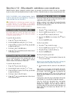
Page 41: ...lication See chapter 12 4 for instructions on how to enable the Bluetooth transmission to a paired device If your PDA is out of reach or if its Bluetooth features are disabled the locator will display...

Page 42: ...ager is compatible with PCs running Microsoft Windows XP 7 8 and 8 1 To send stored data to your paired PDA 1 Ensure your paired PDA is switched on and running the SurveyCERT app 2 Press the key to en...

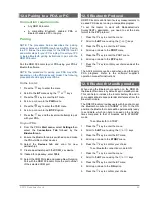
Page 43: ...on 5 Press the key to switch Bluetooth off and return to the previous menu 12 3 Pairing to a transmitter To pair to a transmitter you require a Bluetooth enabled model such as the Tx 5B or Tx 10B Befo...

Page 44: ...rt 12 5 Bluetooth Protocol RD8100 locators can transmit survey measurements to a paired PDA device running a compatible program To set the locator to work with Radiodetection s SurveyCERT application...

Page 45: ...RD8100 wireless Bluetooth technology features Radiodetection recommends resetting the connection and then pairing your device again To reset the wireless connections 6 Press the key to enter the menu...

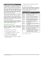
Page 46: ...ency is displayed on screen 2 iLOC commands are sent using the key press it to send the new frequency to the transmitter 3 The locator s LCD will display SEND momentarily and then OK if the transfer i...

Page 47: ...or there may be an error in the connection Move closer to the transmitter and retry the procedure If the connection continues to fail return to the transmitter and reset the connection using the proc...

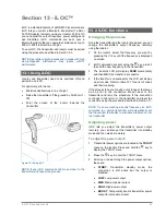
Page 48: ...adiodetection or a Radiodetection approved repair center Regularly check your locator for correct operation using eCert see section 14 6 and the on board Self Test NOTE Service by non approved service...

Page 49: ...e 10 Indicate if you do not wish to receive e mail or other marketing material with new product information or special offers and promotions related to its product range 14 5 Upgrading software From t...

Page 50: ...ame Bag 10 RX AFRAME BAG A Frame replacement lead 10 RX AFRAME LEAD 2 50mm Locator signal clamp 10 RX CLAMP 50 4 100mm Locator signal clamp 10 RX CLAMP 100 5 130mm Locator signal clamp 10 RX CLAMP 130...

Page 51: ...SONDE STD 33 Standard Sonde 8kHz depth up to 5m 10 SONDE STD 8 Standard Sonde 512Hz depth up to 5m 10 SONDE STD 512 Sewer Sonde 33kHz depth up to 8m 10 SONDE SEWER 33 External Shell for heavy duty App...

Page 52: ...10 RX MBATPACK LION K XX Li Ion rechargeable battery mains kit includes mains charger Replace XX with US UK EU or CN Li Ion automotive charger 10 RX ACHARGER LION Li Ion mains charger 10 RX MCHARGER...

Page 53: ...d case 10 RD7K8KCASE USA Miscellaneous Safety equipment Warning triangle 10 WARNING TRIANGLE Calibration Certificates Remote Calibration and PC Software Locator Calibration Certificate per unit reques...

Page 54: ...USA 39 740 Garand Lane Unit B Palm Desert CA 92211 USA Tel 1 800 688 8094 Tel 1 760 343 7350 pearpoint sales us spx com www pearpoint com Radiodetection Canada 344 Edgeley Boulevard Unit 34 Concord On...

Reviews: