© 2015 Radiodetection Ltd
23
Null mode
Null mode is used to verify a locate signal in
environments with limited or no interference or distortion.
Null mode gives a null response when it is directly over
the line.
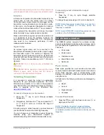
In Null mode the following indicators are displayed by the
LCD:
Signal strength.
Compass.
Right and left arrows.
To select null mode:
1 Press the
key until the null mode icon
is
displayed on the LCD
The sharp, null response can be easier to use than the
Peak response but is vulnerable to interference and
should not be used for locating, except in areas where
there is no interference present.
Guidance Mode offers improved performance in such
conditions while Peak+ mode can combine the Peak
bargraph with Guidance arrows to combine fast and
accurate locate tools.
5.3 Compass
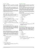
The LCD compass provides a visual indication of the
direction of the target cable, pipe or sonde. The compass
is available for all frequencies apart from Power, Radio
and Passive.
5.4 Trace
Line tracing can be accelerated by switching the locator
to Guidance mode.
Move the locator left and right while walking along the
path of the line to place the target position Needle
directly over the line. As you move the locator over the
line, the left and right arrows (and an accompanying
tone) will indicate if the target line is to the left or right of
the locator.
5.5 Pinpoint
Locating a target line in Peak, or Peak+, mode
accurately defines the position of a target line after it has
been traced and its position is approximately known.
Start with medium output power from the transmitter,
medium frequency on the transmitter and locator, and
Peak or Peak+ mode on the locator.
Set the locator sensitivity to approximately 50% by
pressing the
or
key
NOTE: it may be necessary to adjust the sensitivity level
throughout the pinpointing to keep the bar graph on
scale.
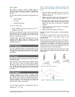
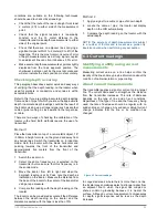
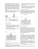
1 With the antenna perpendicular to the line, make
traverses across the line. Define the point of
maximum response.
2 Without moving the locator, turn it round as if it is on
a pivot. Stop at the point of maximum response.
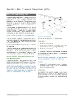
3 Hold the locator vertical with the antenna just above
the ground and move the locator from side to side
across the line. Stop at the point of maximum
response.
4 With the end of the antenna close to the ground,
repeat steps 2 and 3.
5 Mark the position and direction of the line.
Repeat the steps of the procedure to increase pinpoint
accuracy.
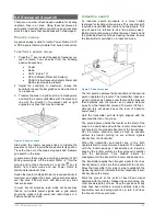
If using Peak+ mode, switch to null arrows by pressing
and holding the
key. Alternatively switch to Null
antenna mode.
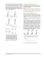
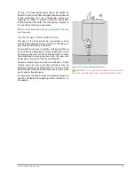
Move the locator to find the Null position. If the position
of the Peak and the Null pinpoints correspond, it can be
assumed that the pinpoint is accurate. The pinpoint is
not precise if the marks do not correspond, but both
marks will show an error to the same side. True line
position will be close to the Peak position.
The line lies half the distance to the other side of the
Peak position as the distance between the Peak and the
Null positions.
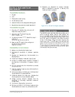
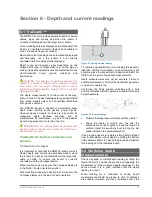
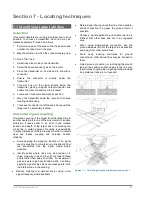
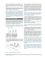
Figure 5.3: Pinpointing with Peak and Null indicators
Figure 5.2: Pinpointing a target line

