background image


Version: 

03 

Date:  

March 16, 2011 

Document:   Sigma 600 Ver 04 


Page 34 of 34 

Date 1

e

 release: January 1, 2003


In

d

u

s

tr

ie

w

e

g

 1

7

4

5

3

8

 A

G

 T

e

rn

e

u

z

e

n

T

h

e

 N

e

th

e

rl

a

n

d

s

T

e

l:


+

3

1

 1

1

5

 6

4

5

4

0

0


F

a

x

 +

3

1

 1

1

5

 6

2

0

0

4

0

C

O

P

Y

R

IG

H

T

 ©

 2

0

0

2

 R

A

D

IO

 Z

E

E

L

A

N

D

 D

M

P

 B

.V

.

A

L

L

 S

IZ

E

S

 I

N

 M

M

A

M

E

R

IC

A

N

 P

R

O

J

E

C

T

IO

N

 S

T

Y

L

E

C

O

M

M

E

N

T

S

:

P

a

g

e

:

S

IG

M

A

 6

0

0

S

IG

M

A

 6

0

0

 s

e

tt

in

g

s

P

ro

je

c

t:

P

a

rt

:

M

.M

a

rt

in

e

t

0

8

-1

0

-2

0

0

2

D

a

te

:

D

ra

w

n

:

F

ile

 n

a

m

e

:

S

iz

e

:

A

4

0

1

 o

0

1

R

e

v

is

io

n

 n

u

m

b

e

r:

A

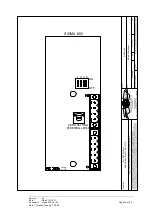
SIGMA 600

STEERING LEVER

OFF

ZERO SETTING

ON

4

3

2

1


Summary of Contents for Sigma 600

Page 1: ......

Page 2: ...Version 03 Date March 16 2011 Document Sigma 600 Ver 04 Page 2 of 34 Date 1e release January 1 2003 ...

Page 3: ...NL P O Box 1070 4530 GB Terneuzen NL declare under our sole responsibility that the product Sigma 600 to which this declaration relates is in conformity with the following standard s or other normative document s EN 60945 IEC 945 Third edition 1996 11 Chapters 9 10 11 and 12 This declaration is issued according to the European Community Directive on Electromagnetic Compatibility 89 336 EEC On beha...

Page 4: ...is fitted with a high voltage EL lamp under the foil and with high voltage electronics in the casing for operation of the lamp Do not abrade or damage the foil and do not open the device during operation Danger of electrocution if the device is used improperly Acht Acht Acht Achtung ung ung ung Dieses Gerät ist mit einer unter Hochspannung stehenden EL Leuchte unter der Folie und mit Hochspannungs...

Page 5: ...ellingen en jumpers Page 14 General description Technical details 15 Installation instructions 16 Connections 19 Operation 20 Adjustment 29 Dimensions control unit 30 Dimensions mounting frame 31 Cut out dimensions console 32 Connections Sigma 600 to Sigma 550 33 Connections Sigma 600 to RZ 903 34 Settings and jumpers Seite 21 Allgemeine Beschreibung Technische Daten 22 Installationsanleitung 23 A...

Page 6: ... Ver 04 Page 6 of 34 Date 1e release January 1 2003 Versie informatie 03 DIPswitch settings description changed in German Description of Dodge function has been re written Screening of cables added in drawings 04 Changed Cover Changed Cut out Drawing ...

Page 7: ...et geval neem dan zo snel mogelijk contact op met uw dealer Lees voor het installeren van de Sigma 600 aandachtig deze manual door Als er vragen of onduidelijkheden zijn neem dan contact op met uw dealer 2 Beschrijving meegeleverde items 1 Manual Hierin is het aansluiten de functionaliteit en de bediening van de Sigma 600 terug te vinden 2 Bedienunit Sigma 600 Voedingsspanning van dit apparaat is ...

Page 8: ...rdt zodanig geplaatst dat deze eenvoudig te bedienen is voor de roerganger De Sigma 600 wordt aangesloten op junctionbox RZ 903 op een andere Sigma 600 of op een Sigma 550 Er kunnen maximaal drie bedienunits in één communicatielijn worden geplaatst Er moet voldoende ruimte overblijven om de bekabeling te leggen Een montage tekening is te vinden achter in deze manual ...

Page 9: ...a 600 blijven werken op de 24V reservevoeding Als er maar 1 voeding wordt gebruikt moet de aansluitingen op de hoofdvoeding worden doorgelust naar de aansluitingen van de reservevoeding Indien dit niet wordt gedaan licht de voedingsspanning LED rood op ten teken dat er een spanningsbron mist Als de Sigma 600 is aangesloten op 2 actieve voedingen dan zal dan zal de voedingsspanning indicator LED gr...

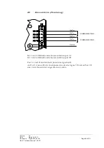
Page 10: ...tie K2 1 en 2 Bidirectionele communicatie poort 1A K2 3 en 4 Bidirectionele communicatie poort 1B Poort 1A en 1B zijn identiek intern door gelust Op poort 1A kan bijv de junctionbox of de Sigma 550 worden aangesloten en op poort 1B een tweede bedienunit Rx Tx COMMUNICATIONS Rx Tx Rx Tx COMMUNICATIONS Rx Tx Screen ...

Page 11: ... met een piloot Sigma 550 kan men op een geselecteerde bediening kiezen of de wegafhankelijke bediening bestuurd wordt door de bijbehorende Sigma 600 of door de piloot waarmee de wegafhankelijke bediening is gekoppeld Is dit laatste het geval dan zal de wegafhankelijke bediening de roerstand van de piloot gaan volgen Door op een geselecteerde bediening op de toets te drukken volgt het roer dat aan...

Page 12: ...de ROT piloot geselecteerd I c m RZ903 Brandt deze LED continu dan is koppelverband geselecteerd Deze LED knippert bij een koers of gyro alarm LED boven Brandt de LED dan is de bediening geselecteerd Knippert deze LED i c m buzzer korte pulsjes dan is de bediening vrijgegeven en kan deze overgenomen worden LED tussen en Brandt deze LED groen dan staat het apparaat aan Brandt deze LED rood dan is e...

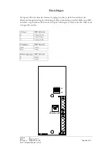
Page 13: ...dres kiezen en met welke bedienunit de Sigma 600 meedimt Dit kan men doen d m v de DIPswitch Indien er slechts één Sigma 600 wordt gebruikt dient het adres op 0 te staan Address DIPswitch 0 1 off 2 off 1 1 on 2 off 2 1 off 2 on Vrijgeven DIPswitch uit 3 off aan 3 on Dimgroep DIPswitch 0 4 off 1 4 on ZERO SETTING STEERING LEVER 1 2 3 4 OFF ON ...

Page 14: ...ent Should this not be the case contact your dealer as quickly as possible Before installing the Sigma 600 read this manual carefully If you have questions or anything is unclear contact your dealer 2 Description of items supplied 2 Manual This describes the connection functionality and the operation of the Sigma 600 4 Operating unit Sigma 600 Supply voltage of this device is 18 36 Vdc The electri...

Page 15: ...e operating unit should be placed such that the helmsman may readily operate it The Sigma 600 should be connected to junction box RZ 903 to another Sigma 600 or to a Sigma 550 A maximum of three operating units may be placed in one communication line Sufficient space must be left to lay the cables A construction drawing will be found at the back of this manual ...

Page 16: ...ma 600 will continue to operate on the 24V back up supply When only 1 supply is used the connections to the main supply should be looped through to the connection of the back up supply When this is not done the supply voltage LED will light up red indicating that a power source is missing When the Sigma 600 is connected to 2 active supplies the supply voltage indicator LED will light up green Shou...

Page 17: ... and 2 Bi directional communication port 1A K2 3 and 4 Bi directional communication port 1B Port 1A and 1B are identical internally looped through The junction box or the Sigma 550 for example may be connected to port 1A and the second operating unit to port 1 B Rx Tx COMMUNICATIONS Rx Tx Rx Tx COMMUNICATIONS Rx Tx Screen ...

Page 18: ...o which the follow up operation is coupled In the latter case the follow up operation will emulate the rudder position of the pilot Depressing the key on a selected operation will cause the rudder that is connected to the follow up operation to follow the setting made on the operation involved Depressing the key on the operation selected will result in the steering lever no longer having any effec...

Page 19: ... flickers during a course or gyro alarm LED above When the LED is on the operation has been selected When this LED flickers in conjunction with buzzer short impulses the operation has been released and may be taken over LED between and When this LED is green the device is on When this LED is red there is a voltage alarm In the event of an alarm the buzzer will activate at all operations whether th...

Page 20: ...e selected as may the operating unit with which the Sigma 600 dims The DIPswitch is employed for this purpose When only one Sigma 600 is used the address should be set to 0 Address DIPswitch 0 1 off 2 off 1 1 on 2 off 2 1 off 2 on Released DIPswitch off 3 off on 3 on Dimming group DIPswitch 0 4 off 1 4 on ZERO SETTING STEERING LEVER 1 2 3 4 OFF ON ...

Page 21: ... unverzüglich an Ihren Händler Bitte lesen Sie dieses Handbuch vor der Installation des Sigma 600 gründlich durch Wenn Fragen oder Unklarheiten auftreten wenden Sie sich bitte an Ihren Händler 2 Beschreibung der mitgelieferten Komponenten 3 Handbuch In diesem Handbuch finden Sie eine Beschreibung der Anschlüsse der Funktionen sowie der Steuerung und der Bedienung des Sigma 600 6 Steuereinheit Sigm...

Page 22: ...ositioniert werden dass sie für den Rudergänger einfach zu bedienen ist Das Sigma 600 wird am Anschlusskasten RZ 903 an einem anderen Sigma 600 oder an einem Sigma 550 angeschlossen Maximal drei Steuereinheiten können über eine Datenleitung versorgt werden Für die Verlegung der Kabel muss genügend Platz frei gehalten werden Eine Montagezeichnung finden Sie hinten in diesem Handbuch ...

Page 23: ...auptversorgung die 24 Volt Reserveversorgung die Funktionen des Sigma 600 Wenn mehr als eine Stromversorgung zugeschaltet wird müssen die Anschlüsse an der Hauptversorgung zur Reserveversorgung durchgeschleift werden Wird dies nicht durchgeführt leuchtet die Kontroll LED für die Stromversorgung rot auf als Zeichen dass eine Stromquelle fehlt Wenn das Sigma 600 an zwei aktive Stromversorgungen ange...

Page 24: ...K2 1 und 2 Bidirektionaler Kommunikationsport 1A K2 3 und 4 Bidirektionaler Kommunikationsport 1B Port 1A und 1B sind identisch intern durchgeschleift An Port 1A kann z B der Anschlusskasten oder das Sigma 550 und an Port 1B eine zweite Steuereinheit angeschlossen werden Rx Tx COMMUNICATIONS Rx Tx Rx Tx COMMUNICATIONS Rx Tx Screen ...

Page 25: ... Wenn ein Alarm anliegt so muss erst der Alarm bestätigt werden bevor die Steuerung übergeben werden kann Wenn die wegabhängige Steuerung mit einem Pilot Sigma 550 verbunden ist kann man am ausgewählten Steuerelement festlegen ob die wegabhängige Steuerung durch das zugehörige Sigma 600 oder durch den Pilot gesteuert wird mit dem die wegabhängige Steuerung verbunden ist In letzterem Fall wird die ...

Page 26: ...nd NMEA des Pilots aufrufbar Mit der Taste wird das Kommando Dodge starboard Links ausweichen an den Piloten gesendet Die Funktion Dodge Ausweichen ist nur bei die Einstellungen COMPASS und NMEA des Pilots aufrufbar 3 Alarme und Signale LED über Wenn diese LED dauerhaft leuchtet wurde die wegabhängige Steuerung aktiviert Bei einem Alarm an der Ruderanlage blinkt diese LED LED über Bei Sigma 550 We...

Page 27: ...ausgewählt werden Wenn das Sigma 600 an ein RZ903 angeschlossen ist so erfolgt das Dimmen des Sigma 600 über ein externes Potentiometer oder die Dimmerwirkung wird durch ein ggf vorhandenes Sigma 100 auf das Sigma 600 übertragen Es besteht ferner die Möglichkeit das Sigma 600 in Kombination mit einem RZ903 auf eine feste Hintergrundbeleuchtung einzustellen Diese wird am RZ903 durch die Software ge...

Page 28: ...nheit die Dimmerwirkung beim Sigma 600 mitregelt Diese Einstellung wird mit Hilfe eines DIP Schalters vorgenommen Wenn nur ein Sigma 600 eingesetzt wird muss die Adresse auf 0 eingestellt werden Adresse DIP Schalter 0 1 aus 2 aus 1 1 ein 2 aus 2 1 aus 2 ein Freigeben DIP Schalter Aus 3 aus Ein 3 ein Dimmergruppe DIP Schalter 0 4 aus 1 4 ein ZERO SETTING STEERING LEVER 1 2 3 4 OFF ON ...

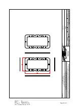
Page 29: ... 620040 The Netherlands 4538 AG Terneuzen Industrieweg 17 RADIO ZEELAND DMP B V AMERICAN PROJECTION STYLE ALL SIZES IN MM COPYRIGHT 2002 RADIO ZEELAND DMP B V COMMENTS 07 10 2002 M Martinet Part Date Drawn Project File name DIMENSIONS HOUSING A4 Size Page SIGMA 600 A O MANUALS SIGMA600 SIG 01 DWG Revision number 01 of 01 SIG 600 ...

Page 30: ... Fax 31 115 620040 The Netherlands 4538 AG Terneuzen Industrieweg 17 RADIO ZEELAND DMP B V AMERICAN PROJECTION STYLE ALL SIZES IN MM COPYRIGHT 2002 RADIO ZEELAND DMP B V COMMENTS 07 10 2002 M Martinet Part Date Drawn Project File name FRAME A4 Size Page SIGMA 600 A O MANUALS SIGMA600 SIG 02 DWG Revision number 01 of 01 ...

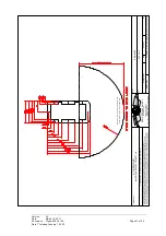
Page 31: ... Terneuzen Industrieweg 17 RADIO ZEELAND DMP B V AMERICAN PROJECTION STYLE ALL SIZES IN MM COPYRIGHT RADIO ZEELAND DMP B V COMMENTS 09 03 2011 M Martinet Part Date Drawn Project File name CUT OUT A4 Size Page SIGMA 600 B O MANUALS Drawings Sigma 600 Cut out DWG Revision number 01 of 01 BUILD IN DEPTH MIN 55mm EXCL CONNECTORS BUILD IN DEPTH 90mm INCL CONNECTORS ...

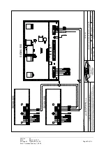
Page 32: ...therlands Tel 31 115 645400 Fax 31 115 620040 COPYRIGHT 2002 RADIO ZEELAND DMP B V ALL SIZES IN MM AMERICAN PROJECTION STYLE COMMENTS Page SIGMA 600 CONNECTION DIAGRAM SIGMA 600 on Sigma 550 Project Part M Martinet 23 08 2004 Date Drawn File name Size A4 01 of 01 Revision number A SCREEN SIGMA 600 SIGMA 550 SIGMA 600 DASHED LINE IS OPTIONAL ...

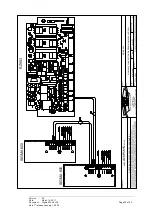
Page 33: ...rneuzen The Netherlands Tel 31 115 645400 Fax 31 115 620040 COPYRIGHT 2002 RADIO ZEELAND DMP B V ALL SIZES IN MM AMERICAN PROJECTION STYLE COMMENTS Page SIGMA 600 SIGMA 900 CONNECTION DIAGRAM SIGMA 600 on RZ 903 Project Part M Martinet 07 10 2002 Date Drawn File name Size A4 01 of 01 Revision number A RZ903 SIGMA 600 SIGMA 600 ...

Page 34: ...Terneuzen The Netherlands Tel 31 115 645400 Fax 31 115 620040 COPYRIGHT 2002 RADIO ZEELAND DMP B V ALL SIZES IN MM AMERICAN PROJECTION STYLE COMMENTS Page SIGMA 600 SIGMA 600 settings Project Part M Martinet 08 10 2002 Date Drawn File name Size A4 01 of 01 Revision number A SIGMA 600 STEERING LEVER OFF ZERO SETTING ON 4 3 2 1 ...

Reviews: