


Installation Manual
Wall Hung Boiler with D.H.W. Storage Cylinder Low Nox – Cod. 99881NA – July 2001
24
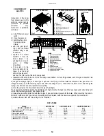
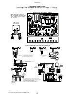
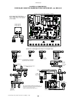
ELECTRICAL CONNECTION FOR
ROOM SEALED COMBUSTION CHAMBER ELECTRONIC IGNITION BOILER – mod. RMAS 24 E
M4
M1
M5
M6
m1
RL1
GAS VALVE
PRESSURE
MODULATOR
42 41
44
46 45
47
48
43
M10
bl
ue
br
ow
n
bl
ac
k
bl
ac
k
bl
ac
k
M.F.
M9
WATER
SWITCH
back
bl
ue
br
ow
n
FA1
PRESSURE
3
C
2
CONTROL
REMOTE
-IN
+
REMOTE SENSOR
TEL
00.0
SEX
T
2
1
M1
00.0
OR TA
OUT-DOOR
2
1
3
m3
IGNITION
OPTIONAL
P.C.B.
N
12
11
10
9
7
8
LB
13
L
L
PS
INTERFACE
N
REMOTE
bl
ac
k
bl
ue
lg
ht
-b
lu
e
brown
br
own
TERMINAL BLOCK
TS
5
12
6
7
8
9
10
11
4
ELECTRONIC IGNITION S4565A20
ELECTRODE
N
L
ATTENTION:
lig
ht-
bl
ue
lig
ht-
bl
ue
RED
CX
FILTRO
NET FILTER
CY
CY
PUMP
P
IG
R
br
ow
n
br
ow
n
M8
or
an
ge
or
an
ge
m2
V
5+ 4-
Z
brown
bl
ac
k
bl
ac
k
red/black
brown
8 7
28
27
26
25
10000 - 25°C
black
E.I
black
black
SENSOR
D.H. WATER
DIVERTOR
AIR PRESS.
SWITCH
FAN
black
31
33
32
34
black
SENSOR
HEATING
VALVE
10000 - 25°C
C
B
6
lig
ht-
bl
ue
lig
ht-
bl
ue
5
4
3 WAY
A
br
ow
n
bl
ac
k
bl
ac
k
br
ow
n
RLA
D4
48
60
B
A
M. RIS
T. RIS
63
31
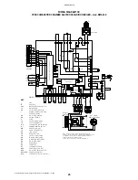
RAVI 2 CIRCUIT BOARD-ELECTRONIC TEMPERATURE INDICATOR WITH SELF-DIAGNOSTIC
WIRING OF COMPONENTS BY MEANS OF CONNECTORS
23
LED5
C6
C7
RS1
R58
R22
R21
4
2
1
3
15
14
22
LED2
LED1
LED3
LED4
RAVI II
R31
42
R18
R17
yellow
blue
R48
FA1
C2
0
R49
R23
R24
R47
C1
9
C2
1
red
brown
R39
C9
M9
R62
R61
R57
J16
R38
+
C5
J20
R37
41
R16
C14
IC2
+
J7
T4
1
2
3
5 4
GP
L
C1
5
R40
R56
ME
T
R43
R33
R15
R32
43
C13
+
C26
R42
44
45
R41
47
J21
R36
46
D1
2
61
R34
24
17
16
18 19
21
20
LED8
LED6
LED7
LED9
LED10
LED11
J2
M1
D2
8 7 6 5
J3
3
4
2 1
35
36
+
C8
J9
C3
R12
R13
+
40
38
IC1
M10
J15
39
37
J13
R5
R2
R20
C1
2
C1
0
J18
M8
CM4
+
34
64
M14
J12
R28
R30
R26
J5
CM3
+
+
+
32
33
RAMIRE 3 CIRCUIT BOARD STANDARD ON ALL MODELS
D8
N.B. M1 CONNECTOR OF THE RAVI 2
52
53
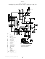
Wiring diagram
+
M13
J10
RISC.
+
C25
R63
R60
59
R59
IC4
P2
TIME CLOCK
M11
D6
49
J11
C24
TR1
D1
1
J1
7
50
51
J6
D1
0
D7
CIRCUIT BOARD MUST BE CONNECTED TO
THE M11 CONNECTOR OF THE RAMIRE 3
CIRCUIT BOARD.
SEC
O
ND
A
R
IO
PR
IM
A
R
IO
57
CM1
RLA
55
54
R55
56
R35
58
IC3
R54
D9
R53
PTC1
25
29
62
P1 SAN.
P4
R29
P5
T1
R25
T3
P3
RL4-RV
D3
D1
T2
R27
J4
D2
M7
30
C22
+
M5
RL2-RS
J2
J4
J1
28
27
24
26
M6
RL1-RP
RL3-RT
R50
R51
D5
M4
14
15
22
M12
23
J3
16
21 20
R52
17
18
19
2AF
FUSE 1
C23
M1
9
M2
13
10
11
12
8
7
3
4
6
M3
5
2
1
N.B.:
IN CASE OF REMOTE CONTROL INSTALLATION, FOR
CORRECT OPERATION, REMOVE LINK BETWEEN TERMINALS TA-OR
ON TERMINAL BLOCK, AND SET SUMMER-WINTER SWITCH OF
CONTROL PANEL ON SUMMER POSITION.
CHECK THE POSITION OF M10 BEFORE I
NSERTING IT.
Summary of Contents for RMA
Page 2: ......


