


Installation Manual
Wall Hung Boiler with D.H.W. Storage Cylinder Low Nox – Cod. 99881NA – July 2001
5
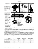
FLUE EXHAUST DIRECTLY
INTO A DUCT (CHIMNEY)
OR COLLECTIVE BRANCH-
TYPE FLUE
VERTICAL EXHAUST
Open chamber model
A maximum of 3 changes of
direction are allowed.
Keep to the distances and
angles shown in the diagram.
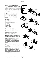
FLUE EXHAUST DIRECTLY
TO OUTSIDE
VERTICAL EXHAUST
Open chamber model
A maximum of 2 changes of
direction are allowed including
the first connection to the
boiler.
Keep to the distances and
angles shown in the diagram
For the flue exhaust from multiple superimposed type "B" gas boilers with natural draught into newly installed collective flues
(CCR) with natural draught, follow the directions set out in the UNI 10640 standard.
It should be noted that these type of flues do not apply in the case of boilers equipped with mechanical means of flue exhaust.
For the FLUE EXHAUST from multiple combined type "C" room sealed gas boilers equipped with exhaust fans into single-
chimney collective flues with natural draft or multiple combined flues, follow the directions set out in the UNI 10640 standard.
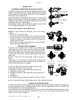
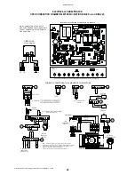
CONNECTION OF FLUE PIPES
All boilers must be connected to a duct for discharging the burnt gasses; the section of this duct must not be less than the
diameter of the pipe coming out of the boiler and must be sealed airtight so that no burnt gasses can leak out. There must be no
long horizontal sections or abrupt deviations along its length (see fig. 1-2).
•
For type B open combustion circuit boilers;
•
connect the boiler to the chimney using a
∅
130 link.
•
For type C12 sealed combustion circuit boilers;
•
KIT A - COAXIAL EXHAUST connect using the
∅
100 - 60 double elbow and 2 coaxial pipes;
∅
60 for EXHAUST of
combustion gasses -
∅
100 for air INTAKE.
•
For type C32 sealed combustion circuit boilers;
•
KIT B – TWIN PIPE SYSTEM connect using 2 sections with a
∅
80 elbow for the EXHAUST of combustion gasses -
∅
80
for air INTAKE.
N.B.:
FLUE KITS are supplied in a separate box.
Fig. 1
Fig. 2
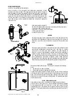
3% minimum
slope
Suction
opening
2.5 m max.
2d
d
3% minimum
slope
2d
d
2.5 m.
max.
1.5
m mi
n.
1 m min.
d
min.
1 m min.
d
3% minimum
slope
2d
2d
2d
3% minimum
slope
Summary of Contents for RMA
Page 2: ......


