


Installation Manual
Wall Hung Boiler with D.H.W. Storage Cylinder Low Nox – Cod. 99881NA – July 2001
13
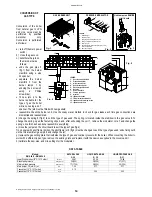
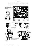
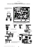
BOILER ADJUSTMENTS
SELECTOR
GPL-MET
NATURAL GAS
L.P.G.
SELECTOR
M5
M11
D6
+
C22
CM3
RS1
J16
R48
R2
3
R2
4
FA1
C2
0
C1
9
C7
C6
C2
1
R47
R17
R49
R1
5
R32
C13
41
R16
C14
R5
7
R6
1
R39
R62
M9
J20
C9
C5
+
R38
42
R31
R37
R1
8
IC2
+
R58
R42
ME
T
43
44
GP
L
R41
C26
+
R43
R4
0
C1
5
R5
6
R3
3
R22
45
46
J7
T4
R21
M13
R63
C25
61
D1
2
47
J21
R3
6
R34
48
D4
R5
9
R6
0
59
A
B
60
+
IC4
J10
+
RISC.
P2
J11
C24
TR1
R1
4
R9
R1
1
R7
+
R12
R8
C3
R1
3
C8
J9
+
C1
7
R10
C1
8
C4
+
C2
7
C1
6
R3
0
R2
8
R2
6
J12
M10
40
FASX4
FASX1
R46
IC1
36
R45
J9
38
R44
39
J15
35
37
R5
C1
2
C1
0
R2
0
FASX2
FASX3
R19
+
R3
R6
R1
R4
C11
J13
J18
CM4
M8
R2
34
33
J4
T3
R29
R25
T1
M14
64
+
+
+
J5
P3
M. RIS
P4
P5
T. RIS
RLA
62
63
32
31
D2
D3
RL4-RV
T2
R27
D1
P1 SAN.
RL2-RS
M7
30
29
D5
PTC1
57
CM1
PR
IM
A
R
IE
SECON
D
O
R
IE
52
53
51
49
50
J1
7
J6
D1
1
D1
0
D7
55
56
R5
5
RLA
54
58
R35
D8
IC3
R53
D9
R54
M1
22
RL3-RT
RL1-RP
J2
J4
24
J1
R5
0
23
25
26
28
27
M12
M6
R51
M4
14
15
16
18
19
17
J3
R52
21 20
FUSE 1
2AF
2
3
4
12
11
9
10
8
7
M2
13
C23
6
5
M3
1
SELECTOR
RLA - CM1
LINK
COMMUTATOR
CM3
LINK
S
TARTING STEP RLA P4
This trimmer is a slow ignition
regulator and it is calibrated at
minimum during factory test.
Use a small screwdriver for any
adjustments. Turn clockwise to
increase gas pressure to the
burner at start-up (by setting
the trimmer to maximum
calibration pressure of
modulator – see page 16).
Turn counter-clockwise to
decrease gas pressure to the
burner at start-up (by setting
the trimmer to the minimum
pressure at start-up will
correspond to minimum
calibration pressure of
modulator –see page 16).
Through the RLA commutator
you can verify the minimum
gas pressure adjusted to the
modulator. Remove the
commutator from the MET-GPL
selector located on the
RAMIRE 2 circuit board and
insert it on the RLA CM1
selector located on the same
circuit board. Once pressure on
the gauge has been checked,
remove the commutator and
insert it on the MET-GPL
selector.
HEATING TIMER
Delays start-up times of the various ignitions once
the boiler has reached optimum temperature (the
range of adjustment is from 0 to 6 minutes, the
value set during testing at the factory, to 2.5 min.)
Use a screwdriver to adjust the delay time. Turn
clockwise to increase time and counter-clockwise
to decrease time down to zero.
MAXIMUM HEATING TRIMMER.
The trimmer is calibrated at 80% of the
max. rated output during factory testing.
For the first ignition of the boiler, adjust
according to heating power of the
system. Use a screwdriver to adjust it.
Turn clockwise to increase, counter-
clockwise to decrease.
THE SELECTOR
MUST BE INSERTED
INTO THE
COMMUTATOR
Summary of Contents for RMA
Page 2: ......


