


Installation Manual
Wall Hung Boiler with D.H.W. Storage Cylinder Low Nox – Cod. 99881NA – July 2001
11
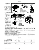
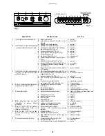
CONTROL PANEL
LEGEND
(see fig. 1)
1.
SUMMER-WINTER ON-OFF SWITCH
2.
LOCK-OUT INDICATOR
3.
HEATING TEMPERATURE ADJUSTMENT KNOB
4.
WATER TEMPERATURE ADJUSTMENT KNOB
5.
SPACE FOR ADDING AN OPTIONAL TIMER
SELF- DIAGNOSTIC
LEGEND (see fig. 2)
6.
OPERATING/ POWER INDICATOR
7.
DOMESTIC HOT WATER OPERATION
8.
HEATING OPERATION
9.
FLASHING LIGHT DENOTING AIR PRESSURE SWITCH FAILURE
10.
FLASHING LIGHT DENOTING DOMESTIC WATER SENSOR FAILURE
11.
FLASHING LIGHT DENOTING HEATING SENSOR FAILURE
12.
FLASHING LIGHT DENOTING 90° C MAX TEMPERATURE SENSOR
FAILURE
13.
FLASHING LIGHT DENOTING FLUE SAFETY - THERMOSTAT FAILURE
14.
FLASHING LIGHT DENOTING LACK OF WATER IN SYSTEM
15.
WATER PRESSURE LEVEL 1 BAR
16.
WATER PRESSURE LEVEL 1.5 BAR
17.
ELECTRONIC TEMPERATURE INDICATOR
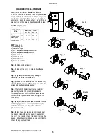
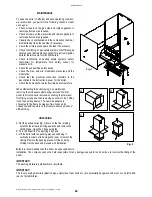
STARTING UP THE BOILER
After connecting up the water supply, before starting up the boiler, carry out the following procedures:
Preliminary procedure
•
Do as follows:
•
make sure the power supply for the boiler is the same as that stated on the plate (230V - 50Hz) and that the live, neutral and
earth connections have been properly connected;
•
make sure the type of gas being supplied is the same as the type for which the boiler has been tested and approved (see
plate data);
•
make sure the unit is properly earthed;
•
make sure there are no flammable liquids or materials in the immediate vicinity of the boiler;
•
make sure that any shut-off valves in the heating circuit are open;
•
open the gas cock and check the gas seals, making sure the counter shows no sign of leaks; in any case, double check by
using a soapy solution and eliminate all eventual leaks. The checking procedure for the gas burner attachment is carried out
with the boiler working;
•
make sure the electrical mains switch is OFF;
•
remove the front cover by pulling it forwards;
•
undo the side screws and rotate the panel downwards
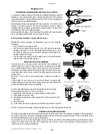
Filling the system
After making sure the gas cock is closed, fill the heating system as follows;
•
fill the system until a pressure of 1.5 bar has been reached (light no. 16 ON; see fig. 2) and then close the filling tap located
under the boiler;
•
make sure the cap on the auto air vent valve is slightly loose to allow air to escape from the system (see fig. 1 pag. 12);
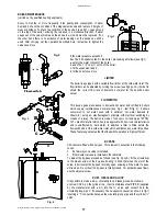
•
undo the cap on the circulation pump to eliminate any eventual air locks (see fig. 1 pag. 13). It is a good idea to purge all
radiators of air at this point too;
•
before starting up the boiler the water pressure must be checked again; if this is seen to be below 0.5 bar (light no. 14
flashes; see fig. 2), bring it back up to 1.5 bar (light no. 16 ON; see fig. 2) and then close the filling tap located ander the
boiler;
•
switch on the electrical power supply to the boiler;
•
turn selector switch 1 to the WINTER
!
position (see fig. 1), after a few seconds the pump will come into action;
•
once the boiler is working, if any noises are heard in the system, repeat the above air purging procedures until there is no air
left in the system;
•
check there are no obstructions in the exhaust duct;
•
check the pressure in the system: if this has gone down and LED 16 (see fig. 2) comes on (pressure gauge shows 1.5 bar)
restore pressure
•
close the filling tap once this operation is completed;
6
7
1
17
10
8
9
11 12 13 14
15 16
2
3
4
5
50
30
40
60
70
80
1
1.5
PRESSURE GAUGE
ELECTRONIC WATER
SELF DIAGNOSTIC
Fig. 1
Fig. 2
Summary of Contents for RMA
Page 2: ......


