SECTION 5: G
ENERAL
S
USPENSION
D
ETAILS
11
SECTION 5: GENERAL SUSPENSION DETAILS
To ens
u
re yo
u
r safety, and comply
w
ith the terms of the
w
arranty, all
u
nits m
u
st be installed in accordance
w
ith
these instr
u
ctions.
The gas or the electrical s
u
pply lines m
u
st not be
u
sed to
s
u
pport the heater.
Do not locate the gas or electric s
u
pply lines directly o
v
er
the path of the fl
u
e prod
u
cts from the heater.
The heater m
u
st be installed in a location that it is readily
accessible for ser
v
icing.
The heater m
u
st be installed in accordance
w
ith
clearances to comb
u
stibles as indicated in this man
u
al.
The minim
u
m and maxim
u
m gas inlet press
u
res m
u
st be
maintained as indicated on the rating plate. Typical
installation config
u
rations are sho
w
n
on Page 12, Figure
18
.
Note: Some modles
w
ill recei
v
e S-hooks (P/N 91907302)
or spring hooks (P/N 91903300), rather than bo
w
shackles.
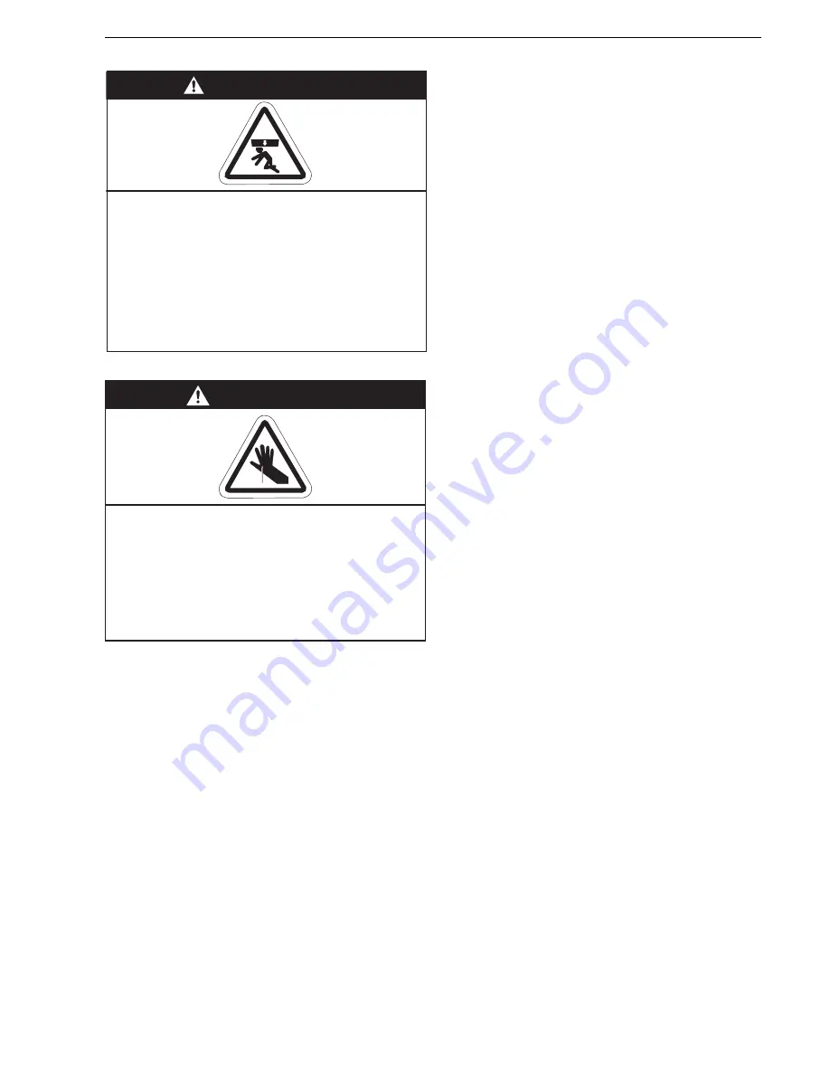
WARNING
Severe Injury Hazard
Secure burner to burner tube with bolts and
lockwashers.
Hang heater with materials with a minimum
working load of 75 lbs (33 kg).
Failure to follow these instructions can result
in death, injury or property damage.
WARNING
Cut/Pinch Hazard
Wear protective gear during installation,
operation and service.
Edges are sharp.
Failure to follow these instructions can result
in injury.
Summary of Contents for BH15UT
Page 2: ......
Page 4: ......
Page 6: ......
Page 33: ...SECTION 7 U TUBE HEATER INSTALLATION 27 Figure 23 U Tube Assembly Overview mm 200...
Page 55: ...SECTION 10 OPTIONAL HEATER ACCESSORIES 49 Figure 28 U Tube Angle Mounted Figure 29 Linear...
Page 71: ...SECTION 16 TROUBLESHOOTING 65 Troubleshooting Flow Chart Linear Double Linear and U Tube...
Page 73: ...SECTION 16 TROUBLESHOOTING 67 Troubleshooting Flow Chart Multiburner...
Page 81: ......


