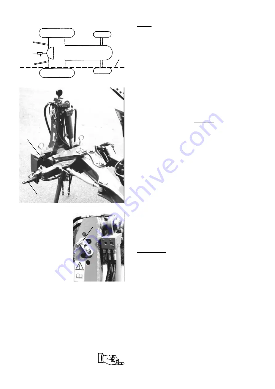
Set-up
Ensure that couplings on the three-point linkages are
compatible (Cat.: Tractor/Plough).
Check tractor tyre pressures and measure the inner
clearance between the tyres. This distance should be
approximately the same for the front and rear wheels,
and the inner walls of the tyres should align (
2/1
).
Set the lower link arms to the same height.
Set the lower link pins (
3/1
) to a height where the
plough can be raised sufficiently, and/or the lower link
arms are in the correct position during operation. (See
tractor operating manual).
Set the top link on the plough head stock so that it lifts
slightly relative to the plough during operation. (Secure
the top link pin to prevent it turning (
4/1
); Fit on the
opposite side a washer and
lynch pin.
Secure the three-point linkage in accordance with
safety regulations.
Connect the hydraulic hoses according to protective
cap colour.
Turnover:
Connect
the
two hoses with the double
acting control unit on the tractor (red);
The hose marked ‘P’ on the hydraulic turnover cylinder
should be used for the ”UP” function.
For single acting turnover use the hose from ”T” direct
into the oil reservoir of the tractor lift and the second
hose to the single acting spool valve.
In this case an additional single-action spool valve is
required for a hydraulically operated pick- up arm for
furrow press operation.
Hydraulic front furrow adjustment:
Connect the two
hoses with a double acting spool valve on the tractor
(blue).
HydroAvant models:
Connect the one hose for the
hydraulic auto reset system with a single-action spool
valve (white).
2
1
3
1
4
1
2
Turnover test
Raise plough. Release parking prop.
Activate the hydraulic control from ”Neutral” into ”UP”
position until the plough has rotated compl. and is flush
with the vertical adjuster screw (
3/2
),
or - in the case of a an hydraulic angling device – until
the re-angling sequence is also completed.
Then put the control back into ”Neutral”.
After about eight seconds, a new turnover sequence or
immediately if the hydraulic control is operated briefly in
”Down” position.
If, when reversing, it emerges that the plough is not
sufficiently raised (despite the lower link pins being
fitted in the bottom position), the lifting rods of the
three-point linkage will need to be shortened.
If this is also not sufficient, attach the top link at a
higher point on the plough.
Beware of the raised plough colliding with other objects,
e.g. the open rear window of the tractor cab, including
when turning.
4


