background image

We reserve the right to make technical changes.

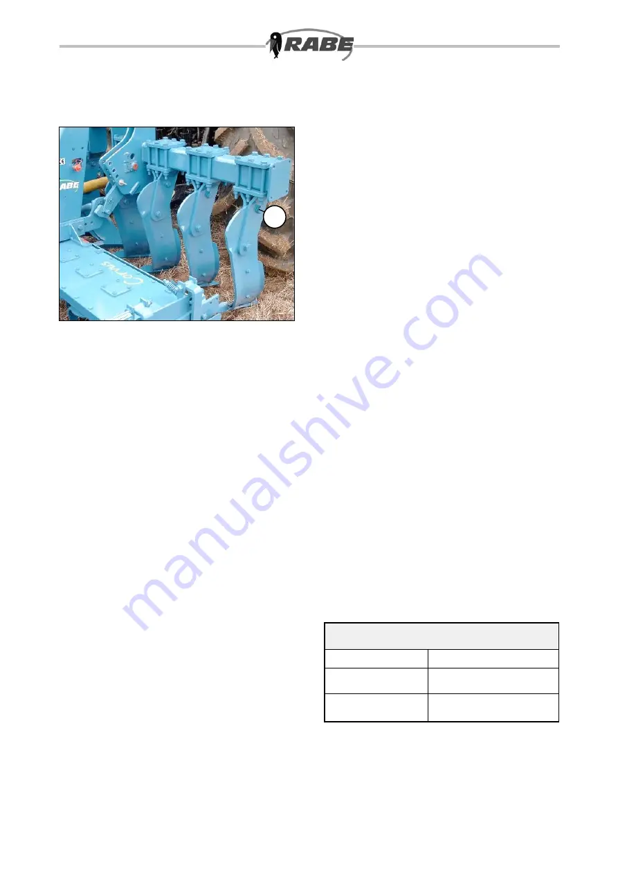
Shearing-pin safety device

The lower one of the two screws (5/1) used to 

secure the tines to the tine holder is configured 

as a shearing pin to protect against overloading. 

If it breaks, a new original screw (M24x1.5x X, 

strength rating 8.8) must be fitted. The upper screw 

should also be checked for damage, and replaced 

if necessary.

5

1

Servicing

Switch off the engine and remove the ignition key 

before working on the attached implement. Do not 

work under a non-secured raised implement.

Provide the raised device with additional support to 

prevent accidental dropping. Before working on the 

hydraulic system, lower the device and release the 

hydraulic pressure.

After approximately eight hours of operation from 

initial startup, retighten all screws and bolts, then 

check for tightness at regular intervals.

Lubricate all bearings regularly with a grease gun 

applied to the greasing nipples. Hose conduits are 

subject to a natural ageing process and should in 

any case be replaced after 5-6 years, regardless of 

their apparent condition.

Residual risks

Danger zone

Note

Shut down the 

entire device 

Operating Instructions: 

Attachment and removal

Connection of the 

complete device

Operating Instructions: 

Safety precautions 

5

Summary of Contents for Combi-Digger Series

Page 1: ...Operating Instructions Subsoiler Combi Digger Order No 9900 01 44GB01...

Page 2: ...he Combi Digger is designed exclusively for normal agricultural use Use for any other purpose counts as unauthorised operation and no liability whatsoever will be accepted for any loss damage or injur...

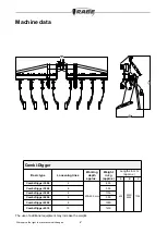
Page 3: ...chine data 2 Combi Digger Basic type Loosening tines Working depth approx Weight in kg approx Lengths in mm approx A B C Combi Digger 3004 4 200 450 mm 800 900 3000 4000 1700 Combi Digger 3006 6 950 C...

Page 4: ...or operating the implement or fol ding in out always check to ensure that no one is standing within its turning circle or operating area DO NOT stand or ride on the implement or remain within its turn...

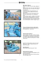
Page 5: ...raulic controls Danger of injury Working depth adjustment Select a length for the upper arm that ensures the horizontal alignment of the device during operation To maintain the depth adjustment the gr...

Page 6: ...Provide the raised device with additional support to prevent accidental dropping Before working on the hydraulic system lower the device and release the hydraulic pressure After approximately eight h...

Page 7: ...it is excee ded the user must take appropriate measures to ensure that there is adequate driver visibility at the farmyard exit road junctions and crossings This can be carried out for example by use...

Page 8: ...We reserve the right to make technical changes Arrangement of warning signs on the device 7 1 2 3 16 For key to symbols see following warning signs...

Reviews: