3
Safety precautions
Do not allow anyone to stand between the tractor
and the device during coupling or uncoupling, even
if this is to allow operation of the external hydraulic
controls. Danger of injury:
The operator should run the machine from the trac-
tor driver’s seat at all times. Always set the tractor’s
hydraulic lifting mechanism to ”attitude control”
before coupling or uncoupling. Check the tractor
and ground loosener before each startup to ensure
that they are in perfect working order for driving
and operation.
Take secure steering into account, by attaching an
adequate counterweight to the front of the tractor if
necessary. Note that there is a danger of crushing
and cutting injuries occurring in the area of the
three-point attachment and folding side sections,
and also around the roller-attachment linkage.
Beware of after-running packer rollers when the
implement is lifted at the end of a fast run; do not
approach until the rollers have come to a complete
stop.
Before moving or operating the implement (or fol-
ding in/out), always check to ensure that no one is
standing within its turning circle or operating area.
DO NOT stand or ride on the implement or remain
within its turning circle or operating area.
Disable the tractor’s hydraulic control system to
prevent accidental operation while the implement is
being towed along public roads. Before leaving the
tractor unattended, lower the implement, switch off
the engine and remove the ignition key.
Carry out all adjustment and maintenance opera-
tions with the implement lowered.
Before operating for the first time – or after a long
period out of use – check all screws and bolts for
tightness, make sure that all bearings are suffi-
ciently greased, examine the hydraulic system for
leaks and check tyre pressures.
The operating pressure of the hydraulic system
must not exceed 200 bar.
- Sound level: < 70 dB(A)
- Maximum length of combination (t device)
12m
- Width 2.55m, maximum 3m
- Maximum height 4m
- Maximum total weight of combination 16t, of
which 20% on front axle.
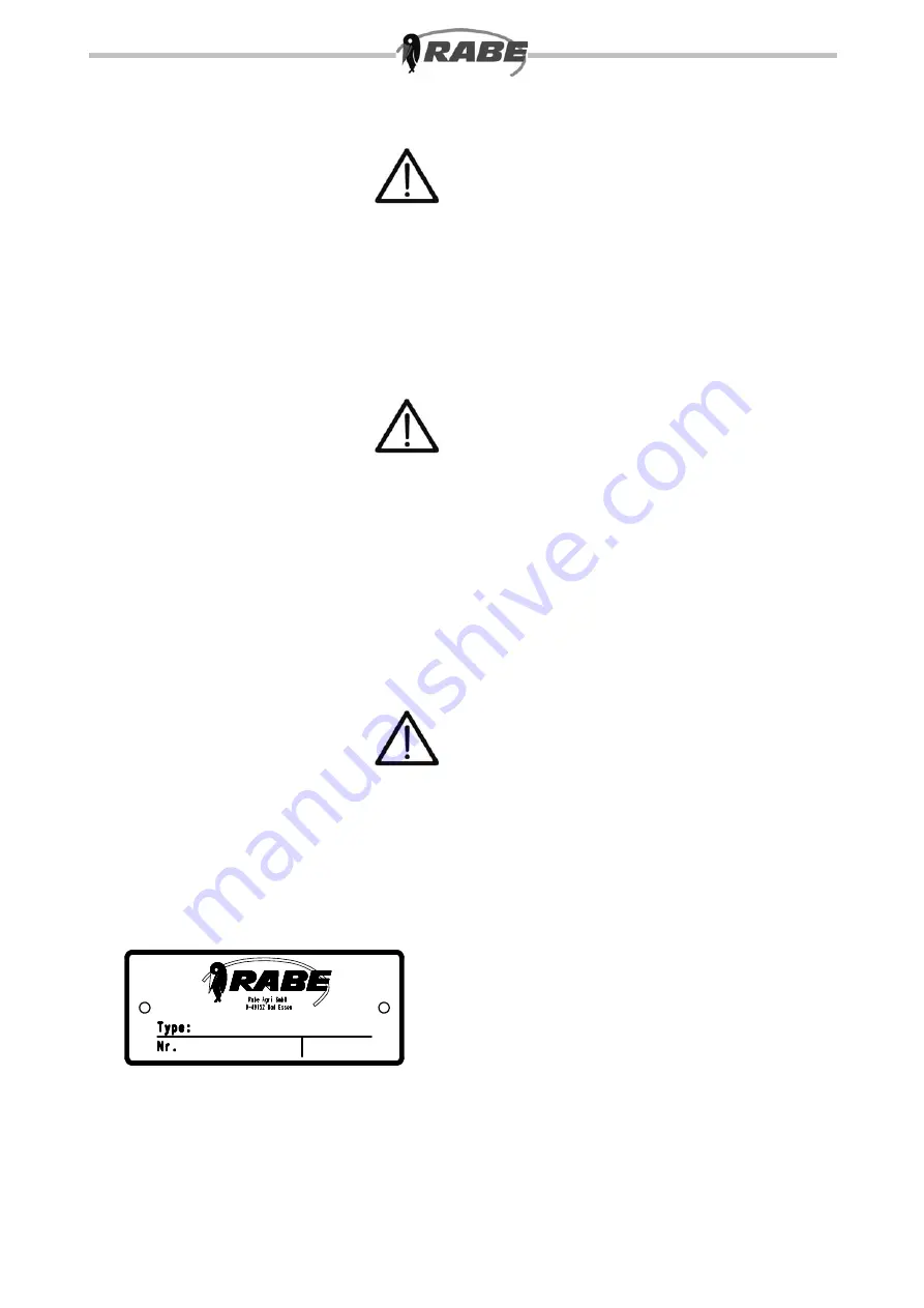
The machine identification plate (3.1) contains cer-
tification details, and must not be altered or made
illegible.
We reserve the right to make technical changes.
3.1


