background image

4

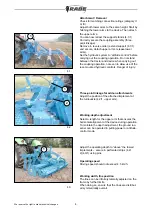
Attachment / Removal

Check for matching connection ratings (category II 

or III).

Adjust both lower arms to the same height. Start by 

hitching the lower arms to the device. Then attach 

the upper arms.

You can now retract the support stands (4.1/1).

Correctly secure the coupling assembly (three-

point linkage).

Remove in reverse order (extend support (4.1/1) 

and secure, detach upper arms, release lower 

arms).

Set the hydraulic system to ”attitude control” before 

carrying out the coupling operation. Do not stand 

between the tractor and device when carrying out 

the coupling operation, not even to allow use of the 

rear-mounted hydraulic controls. Danger of injury: 

Working-depth adjustment

Select a length for the upper arm that ensures the 

horizontal alignment of the device during operation. 

To maintain the depth adjustment, the ground loo-

sener can be operated in pulling-power or attitude-

control mode. 

Operating speed

Driving speed should not exceed 4.5 km/h.

Working width, tine position

The tines can be infinitely laterally adjusted on the 

frame by further limits.

When doing so, ensure that the tines are distribut-

ed symmetrically overall.

4.1

4.3

Adjust the operating depth to ”above” the towed 

implements – secure in perforated strips (4.2/

2)(4.3/1) using pins.

We reserve the right to make technical changes.

1

1

Three-point linkage for add-on attachments

Adjust the position of the attached implement at 

the turnbuckle (4.2/1, upper arm). 

4.2

1

2

Summary of Contents for Combi-Digger Series

Page 1: ...Operating Instructions Subsoiler Combi Digger Order No 9900 01 44GB01...

Page 2: ...he Combi Digger is designed exclusively for normal agricultural use Use for any other purpose counts as unauthorised operation and no liability whatsoever will be accepted for any loss damage or injur...

Page 3: ...chine data 2 Combi Digger Basic type Loosening tines Working depth approx Weight in kg approx Lengths in mm approx A B C Combi Digger 3004 4 200 450 mm 800 900 3000 4000 1700 Combi Digger 3006 6 950 C...

Page 4: ...or operating the implement or fol ding in out always check to ensure that no one is standing within its turning circle or operating area DO NOT stand or ride on the implement or remain within its turn...

Page 5: ...raulic controls Danger of injury Working depth adjustment Select a length for the upper arm that ensures the horizontal alignment of the device during operation To maintain the depth adjustment the gr...

Page 6: ...Provide the raised device with additional support to prevent accidental dropping Before working on the hydraulic system lower the device and release the hydraulic pressure After approximately eight h...

Page 7: ...it is excee ded the user must take appropriate measures to ensure that there is adequate driver visibility at the farmyard exit road junctions and crossings This can be carried out for example by use...

Page 8: ...We reserve the right to make technical changes Arrangement of warning signs on the device 7 1 2 3 16 For key to symbols see following warning signs...

Reviews: