18
We reserve the right to make technical changes.
8. Maintenance instructions
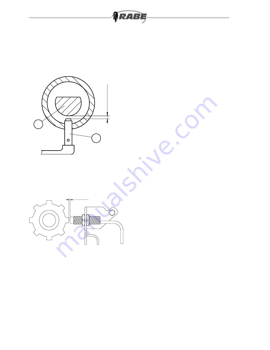
Sensor adjustment: The inductive sensors are set to a
gap of 1-3 mm. To adjust the fan sensor (18.1/1), pro-
ceed as follows: Rotate the fan shaft (18.1/2) so that the
shaft groove is not aligned with the threaded hole of the
sensor. Rotate the sensor by hand up to the fan shaft,
then rotate it back by 3½ turns and lock with the nut. The
sensor is fitted with an LED function indicator so that
“Function of sensor” is displayed whenever a correction
adjustment or test activation takes place.
Use a soft cloth and mild household detergent to remove
any dirt from the drill computer-box (DO NOT use sol-
vents).
DO NOT immerse the housing in liquid.
Disconnect all wires to the electronic terminal box before
carrying out welding work on the tractor or attached
devices, or when charging the tractor battery or connec-
ting a second battery (for carrying out a jump-start).
Given the hygroscopic characteristics of seed (including
dressing agent), the hopper (and dosing wheels) should
be emptied before a long period without operation. Run
the blower briefly to complete the emptying of the seed
conduits. After cleaning, leave the emptying outlet and
rotating cover open, so as not to attract rodents and
other pests. When carrying out cleaning operations,
note that dressing agent is a toxic irritant. Protect such
sensitive parts of the body as the mucous membranes,
eyes and respiratory organs. Do not allow earth or mud
to dry on the coulters. Apply a grease gun to the lubrica-
tion nipples of the bearings at regular intervals (i.e. every
100 hours). A toothed pressure roller will remain in good
condition if it is cleaned after each operation and pro-
tected from corrosion.
Park the Aquila machine in a dry, undercover location,
with its coulters and lane discs clean and protected to
prevent corrosion. Protect the electronic terminal box
(with connection cables) from moisture and store in a dry
place.
Cover the plug socket for the supply cable loom (to
protect from possible soiling). Check the hydraulic hose
conduits at regular intervals and replace any damaged
or brittle items (see list of spare parts). Hose conduits
are subject to a natural ageing process and should be
replaced at intervals of no more than six years. Avoid
directing the hose at the bearings for any length of time,
especially when cleaning the implement with high-pres-
sure water. (The inductive sensors on the monitoring
devices are set to a gap of 1 - 3 mm (18.2). The sensor
is fitted with an LED function indicator so that “Function
of sensor” is displayed whenever a test activation takes
place. For details of sensor adjustment, (see mainte-
nance instructions).
1 - 3mm
18.2
1 -
3
m
m
18.1
1
2


