

Hardware Connections
Step 1 — Attach Module to Prototyping Board
Turn the RCM3900 module so that the Ethernet jack is facing the direction shown in Figure 1 below. Align
the pins from the module’s headers J61 and J62 on the bottom side of the module into header sockets JA and
JB on the Prototyping Board. The
microSD™
Card
does not have to be inserted into connector J2 on the
RCM3900 at this time—there is a protective space insert that you simply pull out before inserting a
microSD™
Card
for the first time.
Figure 1. Install the RCM3900 Module on the Prototyping Board
NOTE:
It is important that you line up the pins on headers J61 and J62 of the RCM3900 module exactly
with the corresponding pins of sockets JA and JB on the Prototyping Board. The header pins may
become bent or damaged if the pin alignment is offset, and the module will not work. Permanent
electrical damage to the module may also result if a misaligned module is powered up.
Press the module’s pins firmly into the Prototyping Board sockets—press down in the area above the header
pins using your thumbs or fingers over the header pins as shown in Figure 1. Do
not
press down on the
microSD™
Card
connector (J2) even if the
microSD™
Card
is installed, but rather press down on the cir-
cuit board along the edge by the connector. Also, do
not
press down on the middle of the RCM3900 module to
avoid flexing the module, which could damage the module or components on the module.
Should you need to remove the RCM3900 module, grasp it with your fingers along the sides by the connec-
tors and gently work the module up to pull the pins away from the sockets where they are installed. Do
not
remove the module by grasping it at the top and bottom.
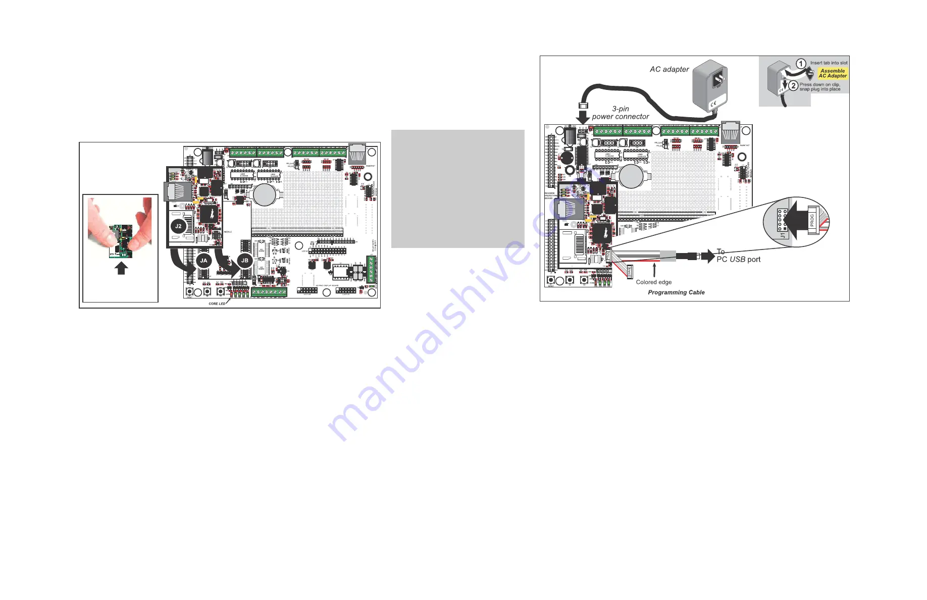
Step 2 — Connect Programming Cable
The programming cable connects the RCM3900 to the PC running Dynamic C to download programs and to
monitor the RCM3900 module during debugging.
Connect the 10-pin connector of the programming cable labeled
PROG
to header J1 on the RCM3900 as
shown in Figure 2. Be sure to orient the marked (usually red) edge of the cable towards pin 1 of the connec-
tor. (Do not use the
DIAG
connector, which is used for a normal serial connection.)
RCM3900
Do not press down
here or on
microSD Card holder
Figure 2. Connect Programming Cable and Power Supply
Step 3 — Connect Power
Once all the other connections have been made, you can connect power to the Prototyping Board.
First, prepare the AC adapter for the country where it will be used by selecting the plug. The RCM3900
Development Kit presently includes Canada/Japan/U.S., Australia/N.Z., U.K., and European style plugs.
Snap in the top of the plug assembly into the slot at the top of the AC adapter as shown in Figure 2, then
press down on the spring-loaded clip below the plug assembly to allow the plug assembly to click into
place. Release the clip to secure the plug assembly in the AC adapter.
Connect the AC adapter to 3-pin header J1 on the Prototyping Board as shown in Figure 2. The connector
may be attached either way as long as it is not offset to one side—the center pin of J1 is always connected
to the positive terminal, and either edge pin is ground.
Plug in the wall transformer. The red
CORE
LED on the Prototyping Board (shown in Figure 1) should
light up. The RCM3900 and the Prototyping Board are now ready to be used.
NOTE:
A
RESET
button is provided on the Prototyping Board next to the battery holder to allow
a hardware reset without disconnecting power.
CAUTION:
You will sense a soft click
once you insert the
microSD™ Card
completely. To remove it, gently press
the card towards the middle of the
RCM4300 — you will sense a soft click
and the card will be ready to be removed.
Do
not
attempt to pull the card from the
socket before pressing it in — otherwise
the ejection mechanism will get dam-
aged. The ejection mechanism is spring-
loaded, and will partially eject the card
when used correctly.


