198
Rabbit 2000 Microprocessor
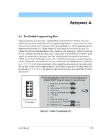
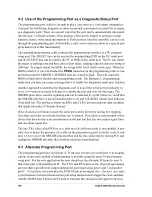
A.2 Use of the Programming Port as a Diagnostic/Setup Port
The programming port, which is already in place, can serve as a convenient communica-
tions port for field setup, diagnosis or other occasional communication need (for example,
as a diagnostic port). There are several ways that the port can be automatically integrated
into the user’s software scheme. If the purpose of the port is simply to perform a setup
function, that is, write setup information to flash memory, then the controller can be reset
through the programming port, followed by a cold boot to start execution of a special pro-
gram dedicated to this functionality.
The standard programming cable connects the programming interface to a PC program-
ming port. The /RESET line can be asserted by manipulating DTR on the PC serial port
and the STATUS line can be read by the PC as DSR on the serial port. The PC can restart
the target by pulsing reset and then, after a short delay, sending a special character string at
2400 bps. To simply restart the BIOS, the string 0x80, 0x24, 0x80 can be sent. When the
BIOS is started, it can tell whether the
PROG
connector on the programming cable is con-
nected because the SMODE1, SMODE0 pins are sensed as high. This will cause the
BIOS to think that it should enter programming mode. The Dynamic C programming
mode then can have an escape message that will enable the diagnostic serial port function.
Another approach to enabling the diagnostic port is to poll the serial port periodically to
see if communication needs to begin or to enable the port and wait for interrupts. The
SMODE pins can be used for signaling and can be detected by a poll. However, recall that
the SMODE pins have a special function after reset and will inhibit normal reset behavior
if not held low. The pull-up resistors on RXA and CLKA prevent spurious data reception
that might take place if the pins floated.
If the clocked serial mode is used, the serial port can be driven by having two toggling
lines that can be driven and one line that can be sensed. This allows a conversation with a
device that does not have an asynchronous serial port but that has two output signal lines
and one input signal line.
The line TXA (also called PC6) is zero after reset if cold boot mode is not enabled. A pos-
sible way to detect the presence of a cable on the programming port is for the cable to con-
nect TXA to one of the SMODE pins and then test for the connection by raising PC6 and
reading the SMODE pin after the cold boot mode has been disabled.
A.3 Alternate Programming Port
The programming port uses serial port A. If the user needs to use serial port A in an appli-
cation, an alternate method of programming is possible using the same 10-pin program-
ming port. For his own application the user should use the alternate I/O pins for port A
that share pins with parallel port D. The TXA and RXA pins on the 10-pin programming
port are then a parallel port output and parallel port input using pins 6 and 7 on parallel
port C. Using these two ports plus the STATUS pin as an output clock, the user can create
a synchronous clocked communication port using instructions to toggle the clock and data.
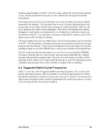
Another Rabbit-based board can be used to translate the clocked serial signal to an asyn-
Summary of Contents for 2000
Page 1: ...Rabbit 2000 Microprocessor User s Manual 019 0069 041018 M...
Page 12: ...6 Rabbit 2000 Microprocessor...
Page 46: ...40 Rabbit 2000 Microprocessor...
Page 54: ...48 Rabbit 2000 Microprocessor...
Page 76: ...70 Rabbit 2000 Microprocessor...
Page 96: ...90 Rabbit 2000 Microprocessor...
Page 142: ...136 Rabbit 2000 Microprocessor...
Page 154: ...148 Rabbit 2000 Microprocessor...
Page 170: ...164 Rabbit 2000 Microprocessor...
Page 174: ...168 Rabbit 2000 Microprocessor...
Page 180: ...174 Rabbit 2000 Microprocessor...
Page 202: ...196 Rabbit 2000 Microprocessor...
Page 206: ...200 Rabbit 2000 Microprocessor...
Page 226: ......
Page 230: ...224 Rabbit 2000 Microprocessor...

