background image


Quincy Compressor

1312100602, September 2012 

16 

3501 Wisman Lane, Quincy IL - 62305-3116

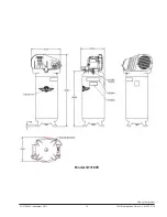
Model Q13160V

Summary of Contents for Q12120P

Page 1: ...ation and must be carefully read in its entirety and understood prior to installation by all personnel who install operate and or maintain this product Manual No 1312100602 September 2012 Edition Single Stage Compressors Instruction Parts Manual ...

Page 2: ... thirty 30 days of your purchase of this compressor or at the time service is requested you must be prepared to provide proof of purchase in the form of a receipt or invoice All moving shipping and insurance charges incurred by you to deliver this compressor to the nearest authorized warranty repair center shall be paid by you and shall be your exclusive responsibility All risk of loss or damage t...

Page 3: ...ompressor unit sold by Quincy Compressor is hereby warned that failure to ob serve the safety precautions and proce dures outlined in this manual may result in serious personal injury damage to property and may void your warranty Quincy Compressor must authorize all warranty service Before contacting your distributor or the factory check the maintenance requirements and the troubleshooting guide f...

Page 4: ...elay will stop the unit if the motor becomes overheated Causes for overheating of the motor can be found in TROUBLESHOOTING Once the overload relay has been tripped the motor must cool and the red overload button on the motor must be reset be fore the unit will start CAUTION Overload relays are designed to protect the motor from damage due to motor overload If the overload relaytripspersistently D...

Page 5: ...lve allows the operator to control the air pressure setting of the compressor discharge A gauge is provided to indi cate the air pressure Pressure Relief Valves Pressure relief valves aid in preventing system fail ures by relieving system pressure when com pressed air reaches a predetermined pressure level All air receivers must be equipped with an adequately sized pressure relief valve This type ...

Page 6: ...ING Oil and moisture residue must be drained from the air receiver daily or after each use Accumulations of oil residue in the receiver can be ignited by em bers of carbon created by the heat of compression causinganexplosion damagetopropertyandinjury to personnel WARNING Follow ASME code for air receiver tanks and other pressurecontainingvessels Pressurevesselsmust not be mod ified welded on or r...

Page 7: ... Lubrication Step 2 Make sure all pressure relief valves are cor rectly installed Refer to SYSTEM COMPO NENTS Step 3 Be sure all guards are in place and securely mounted Refer to SYSTEM COMPO NENTS Step 4 Check all hoses and fittings for weak or worn conditions and replace if necessary Step 5 Check fuses circuit breakers and overload relays for proper sizes Step 6 Open the tank drain valve in the ...

Page 8: ...t relieving the system pressure Give compressor overall visual inspection and be sure safety guards are in place Check for any unusual noise or vibration Weekly Pull on the ring of the pressure relief valves to make sure they are operating correctly Air pressure should escape when the ring is pulled refer to Fig 3 Check all pressurized components for rust crack ing or leaking Immediately discontin...

Page 9: ...st be removed Prior to re moving the belt guard follow the procedures outlined under MAINTENANCE Check the belt alignment by placing a straightedge against the face of the flywheel touching its rim at two places refer to Fig 6 Adjust the flywheel or motor pul ley so that the belt runs parallel to the straightedge Use a wheel puller to move the motor pulley on the shaft Fig 7 Typical Belt Adjustmen...

Page 10: ... from circuit being used 3 Replace check valve or un loader 4 Check with voltmeter 5 Replace with correctly sized motor 6 Check for proper size fuse 7 Replace motor 8 Change power cord voltage of motor to match voltage of power source PROBLEM CAUSES CORRECTION 1 Plug power cord in 2 Switch to auto 3 Turn OFF AUTO switch to the OFF po sition Push the motor thermal over load red button firmly until ...

Page 11: ...Replace motor 12 Move the compressor to a well ven tilated area 13 Change power cord voltage of motor to match voltage of power source PROBLEM CAUSES CORRECTION 1 Realign or tighten pulley and fly wheel 2 Take to Authorized Service Center 3 Tighten belt refer to Belt Align ment Adjustment 4 Shim to level surface fasten to floor if possible 1 Pulley flywheel misaligned or loose 2 Bent crankshaft 3 ...

Page 12: ...ulty regulator 11 Insufficient pressure at tool or acces sory 1 Contact qualified electrician 1 Reversed wiring polarity 10 Compressor runs backwards 1 Change lubricant Move compressor or air inlet to less humid atmosphere 1 Water in lubricant due to humidity or condensation 9 Crankcase lubricant is milky 1 Take to Authorized Service Center 1 Damaged inlet reed valve 8 Air blowing from inlet filte...

Page 13: ...ore head valves fail ing to seat properly 7 Damaged cylinder head gas ket 8 Restriction in head or check valve 15 Compressor overheats 1 Replace defective pressure switch 2 Limit the air pressure to the com pressor s capacity Either use a smaller tool or a larger compressor 1 Defective pressure switch 2 Compressor incorrectly sized 14 Compressor unit runs continu ously 1 Drain tank after every use...

Page 14: ...itch Regulator Valve Cord Rubber Foot Pressure Gauge Tank Wheel Motor Valve Plate Drain Valve Check Valve i S T l S Parts List QTY PART NUMBER DESCRIPTION 1 1312100119 B2800 Compressor 1 6229024900 Valve Plate 1 1312100388 Motor 1 1312100603 Tank 1 1312100170 Check Valve 1 1312100455 Pressure Switch 1 1312100005 Relief Valve 2 1312100006 Pressure Guage 1 1312100213 Discharge Tube 1 6229020500 Air ...

Page 15: ...00123 B3800 Compressor 1 6229024900 Valve Plate 1 1312100390 Motor 1 1312100604 Tank 1 1312100170 Check Valve 1 1312100455 Pressure Switch 1 1312100005 Relief Valve 1 1312100028 Pressure Guage 1 1312100207 Discharge Tube 1 6229020500 Air Filter Kit 1 1312100360 Drain Valve 1 6214343100 Belt Guard Front 1 2236110472 Belt Guard Back 1 1312100442 Drive Pulley 1 1312100134 Drive Belt 1 1312100162 Ball...

Page 16: ...Quincy Compressor 1312100602 September 2012 15 3501 Wisman Lane Quincy IL 62305 3116 DECALS AND DIMENSIONS Model Q12120P Model Q12126VP ...

Page 17: ...Quincy Compressor 1312100602 September 2012 16 3501 Wisman Lane Quincy IL 62305 3116 Model Q13160V ...

Page 18: ...rty 30 days after receipt of notification of readiness for shipment Claims for shortages will be deemed to have been waived if not made in writing with ten 10 days after the receipt of the material in respect of which any such shortage is claimed Seller is not responsible for loss or damage in transit after having received In Good Order receipt from the carrier All claims for loss or damage in tra...

Reviews: