background image

24

INSTALLATION AND USE MANUAL 

QNN 

- REV000A

EN

10 - Using the control interface
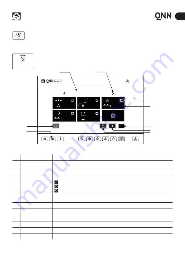
10.8 - Lighting

SALONE PRINCIPALE

Lighting

3

4

6

7

8

9

5

1

 Lighiting home


button

2

NR

DESCRIPTION

OPERATION

1

Light room

internal or external compartment, room or cabin featuring lighting equipment grouped in one 

or more luminous zones, identified by a name defined by the user.

2

Arrow keys

Display of the environments created (Ability to create a maximum of 10 environments)

3

Light source

Ability to manage the chosen light source type: 


RGB (Coloured): Management of colour bar and Zone light intensity Dimmer


DYNAMIC white (Light Yellow) Colour Temperature and Dimmer management.


 MONOCHROMATIC (White) Dimmer management

4

Digital button

command button that appears on the Command Home page at the end of zone association 

operation. 

5

Power/OFF (orange)

By keeping this button pressed for 2 seconds, all zones are simultaneously turned OFF.

6

Menù functions

This button allows accessing the MENU functions:

1. Extra: access to further settings.

2. All the lights in all environments will be turned OFF.

7

Zone Button

To display the other light areas present in the environment (max 12 areas)

8

Power 100% (green)

By keeping this button pressed for 2 seconds, all zones are turned ON at maximum power.

9

Setup Lighting

Ability to configure and change environments, areas, and lights. (Ref. page 24 Chap 10.6).

LIGHTING 

- Management page of the Lighting Quick products.

Switching on/off of lights and colour/tone management. Follow the configuration procedure on page 24, chapter 10.7.

Activation of Lighting function. When the QNN is installed or updated, the key representing the lighting 

function in the HOME screen will appear inactive (GHOST). To activate it, hold down the lighting key until it 

activates it

More information 

- LDIM Manual for connections 

Summary of Contents for QNN

Page 1: ...REV 000A Gateway QNN INSTALLATION AND USE MANUAL EN Pag 4 GATEWAY QNN INTERFACE a a m Gyro 1 Speed 0...

Page 2: ......

Page 3: ...ay Installation Pag 9 6 Electrical connection Pag 10 7 Functioning of the appliance Pag 14 7 0 Control Panel Pag 14 7 1 LED specifications Pag 14 8 Installation on Chartplotter Pag 15 8 0 Installation...

Page 4: ......

Page 5: ...functions Compatible Quick accessories Anchoring system Thruster Battery chargers Stabilazer MC Quick Gyro Lighting 1 1 Main features Management of Quick accessories Compact and practical design inte...

Page 6: ...Serial port RS 485 CAN bus port 2 optical isolation 1kV LED indicators 5 Power Ethernet status RATING Supply da 9 a 32 Vdc Current absorption 0 15A max at 24 Vdc ENVIRONMENTAL CHARACTERISTICS Operatin...

Page 7: ...errors in translation between the translated version and the original text in the Italian language reference will be made to the Italian text This document contains the instructions that are necessar...

Page 8: ...tions CLEANING THE APPLIANCE DO NOT USE solvents or fuels to clean the appliance DO NOT REMOVE the safety labels on the equipment 4 2 Environmental requirements We recommend positioning the stabilizer...

Page 9: ...iteria The appliance must be positioned so that it can easily be reached by the operator Choose a clean smooth flat location The fastening points should be on a level surface The holes must not weaken...

Page 10: ...2 ETH 1 PORT GYRO STABI 5 USB PORT SOFTWARE UPGRADE 3 CAN 1 PORT CHC SRC NRG INVERTER 6 CAN 0 PORT PCS SYSTEM ANCHORING SYSTEM THRUSTER CONNECTION OF GATEWAY QNN ALIMENTAZIONE 4 9 9 9 8 8 8 1 5 2 6 3...

Page 11: ...CRIPTION 1 SHIELD 2 3 GND 4 CAN H 5 CAN L PIN DESCRIPTION 1 TX 2 TX 3 RX 4 RX 5 SHIELD PIN DESCRIPTION COLOR 1 RTS TX 1 BROWN 2 TX 1 BLUE 3 CTS RX 1 WHITW 4 RX 1 GREEN 5 RX 2 NOT INCLUDED YELLOW 6 CTS...

Page 12: ...M M CAN TERMINATOR F A RC REMOTE CONTROL MC Quick Gyro B Control CHC when terminator is not built in C LDIM BUS RGBW D Battery charger E PCS Gateway E PCS Gateway Proportional control PCS system ANCH...

Page 13: ...l PCS NCG T Gateway Thruster PCS NCG W Gateway windlass ANCHORING SYSTEM 0 0 meter V out 0 0 V 0 0 m I out V out 0 0 V 0 0 m I out 0 0 rolling reduction BATTERY CHARGERS SINE WAVE INVERTER LIGHTING TH...

Page 14: ...Y CONNECTED LED POWER GREEN LED STATUS DESCRIPTION OFF GREEN OFF NO POWER ON GREEN ON OPERATING MODE OPERATION COMPLETED SUCCESSFULLY GREEN FLASHES SLOWLY ERROR DURING THE LAST OPERATION GREEN FLASHES...

Page 15: ...mpleting the electrical connections just connect the Gateway to the Chart plotter Thanks to the plug play system all of the calibrations made on the Quick products systems or from the chart plotter ar...

Page 16: ...ctions The detailed instructions for use can be found in the following In Home it shows the general settings in each page it shows the settings for the page shown QNN ICON 10 0 Start QNN After perform...

Page 17: ...ucts connected in the active inactive phase The Quick accessories that can be applied to the QNN are Windlass Thrusters Gyroscopic Stabilizers Battery Charger Inverter currently not available Lights A...

Page 18: ...t of measure 3 save load setting Backup Use a formatted USB drive to perform the backup insert the drive and press SAVE The backup was successful if the folder is found on the drive 4 Clear device lis...

Page 19: ...chor Quick control panels can be connected to the PCS family version 62 37 and the CHC version 2 15 and later for use and installation of the control panels refer to the dedicated manuals PCS CONNECTI...

Page 20: ...hor 4 Zero set key Reset the measure of chain lowered This option is to be used during installation or when the chain counter s reading does not match the actual length of the chain lowered 5 Setup An...

Page 21: ...unctions 2 Manoeuvring keys with proportional control Proportional power manoeuvring control keys choice of 25 50 75 and 100 power possible only with L R bow rotation and L R stern rotation keys 3 Blo...

Page 22: ...Gyro Angle Precession angle 4 ON OFF Button Key to turn on the gyroscope if single gyroscopes with the multi stabilizer option 5 Gyro sliding bar List of connected gyros and status display 6 Setup Gyr...

Page 23: ...eral battery chargers at the same time More information Manual RDS NR DESCRIPTION OPERATION 1 Status Indication of the battery charger status 2 Mode Charging characteristics Float Absorption Bulk Char...

Page 24: ...tion 5 Power OFF orange By keeping this button pressed for 2 seconds all zones are simultaneously turned OFF 6 Men functions This button allows accessing the MENU functions 1 Extra access to further s...

Page 25: ...rea management page changes according to the type of light source Pay attention to the selection 7 Selection of light source type Based on the type of source chosen there are different options Choice...

Page 26: ...er cannot communicate with the QNN make sure the IP address on the RC remote controls is different than the one in the QNN If the two addresses are identical contact Quick customer service for assista...

Page 27: ......

Page 28: ...QUICK S p A Via Piangipane 120 A 48124 Piangipane RAVENNA ITALY Tel 39 0544 415061 Fax 39 0544 415047 www quickitaly com quick quickitaly com REV 000A USER MANUAL Product serial code...

Reviews: