RTA 515ENI-N34, Product User Manual
The RTA 515ENI-N34 is a high-quality product equipped with advanced features. Enhance your user experience by accessing the detailed instruction manual, available for free download on our website. Discover the optimal way to utilize this product's capabilities and unlock its full potential by referring to the comprehensive user manual at manualshive.com.
Share
Download


Reviews:
No comments
Related manuals for 515ENI-N34

TA Series
Brand: Yeastar Technology Pages: 17

WAGO 750-8212/000-100
Brand: Viessmann Pages: 36

SSP-S410
Brand: Symantec Pages: 2
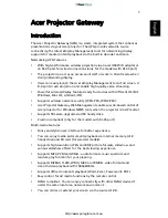
Projector Gateway
Brand: Acer Pages: 58

DG/S 1.1
Brand: ABB Pages: 111

ARR600
Brand: ABB Pages: 72

MicroSCADA Pro SYS 600C
Brand: ABB Pages: 42

Ability ATT-VZN SIM card ready gateway
Brand: ABB Pages: 16

Ekip E-Hub
Brand: ABB Pages: 41

M2302
Brand: ABB Pages: 280

Lon SPA-ZC 100
Brand: ABB Pages: 16
SX2830
Brand: Acer Pages: 113

SpeedTouch 510
Brand: Technicolor - Thomson Pages: 21

4752224007131
Brand: MikroTik Pages: 22

SecPath M9000-AI-E16
Brand: H3C Pages: 128

SMART GATEWAY
Brand: L&S Pages: 28

GW-7228
Brand: ICP DAS USA Pages: 48

VMG1312-T20A
Brand: ZyXEL Communications Pages: 2


