background image

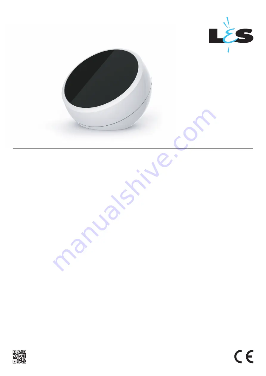
025-FIS18_Smart_GATEWAY

1

Wi-Fi command interface / RF 433.92 MHz for connection between L&S 
receivers and devices with Wi-Fi connection.


INDEX

1 - PRODUCT FEATURES

1.1 - TECHNICAL DATA


1.2 - USE

2 - NETWORK CONFIGURATION

2.1 - INTRODUCTION


2.2 - PROCEDURE FOR USING A HOTSPOT CONNECTION


2.3 - PROCEDURA PER L’UTILIZZO CON RETE WIFI ESISTENTE

3 - SYSTEM CONFIGURATION

3.1 - INTRODUCTION


3.2 - CREATING A DEVICE / ASSOCIATING THE DEVICE WITH THE RECEIVER


3.3 - DELETING OR MODIFYING A CREATED DEVICE


3.4 - CREATING A GROUP


3.5 - DELETING OR MODIFYING A CREATED GROUP

4 - GENERAL SETTINGS
5 - USER INTERFACE WINDOWS

5.1 - INTRODUCTION


5.2 - HOMEPAGE/DEVICES


5.3 - ZONES


5.4 - SCENARIOS


5.5 - PROGRAMMING THE TIMER

6 - FURTHER DETAILS


6.1 - CREATING A QUICK ACCESS COMMAND


6.2 - VERIFY THE NETWORK IP ADDRESS

7 - RECALL A SCENARIO USING TRANSMITTER

7.1 - INTRODUCTION


7.2 - ASSOCIATION OF THE TRANSMITTER


7.3 - ASSOCIATING A SCENARIO WITH THE TRANSMITTER KEY


7.4 - DELETING A TRANSMITTER

8 - RESET THE SYSTEM

8.1 - RESET THE NETWORK CONFIGURATION


8.2 - RESET THE SYSTEM CONFIGURATION

SMART 

GATEWAY

This device complies with Part 15 of the FCC Rules. Operation is subject to the
following two conditions: (1) this device may not cause harmful interference, and (2)
this device must accept any interference received, including interference that may
cause undesired operation.

Summary of Contents for SMART GATEWAY

Page 1: ...ETTINGS 5 USER INTERFACE WINDOWS 5 1 INTRODUCTION 5 2 HOMEPAGE DEVICES 5 3 ZONES 5 4 SCENARIOS 5 5 PROGRAMMING THE TIMER 6 FURTHER DETAILS 6 1 CREATING A QUICK ACCESS COMMAND 6 2 VERIFY THE NETWORK IP ADDRESS 7 RECALL A SCENARIO USING TRANSMITTER 7 1 INTRODUCTION 7 2 ASSOCIATION OF THE TRANSMITTER 7 3 ASSOCIATING A SCENARIO WITH THE TRANSMITTER KEY 7 4 DELETING A TRANSMITTER 8 RESET THE SYSTEM 8 1...

Page 2: ...ers Number of controllable receivers Protection rating Operating temperature Dimensions 1 PRODUCT FEATURES Picture 1 1b A KEY Y key reset network configuration if reset in hotspot with default password See paragraph 7 1 LED A Red green blue lights turn on in sequence when powered ON Flashes red while creating connectiong to a network Blue light turn on if you set connecting to an existing network ...

Page 3: ... the hub can also be accessed when connected to the existing network The first solution is ideal for locations where no Wi Fi network is available but you wish to use a personal device for driving the loads The second solution makes it possible to remain connected to existing Wi Fi networks e g have internet access while using the hub at the same time According to the specifications of the system ...

Page 4: ...EP5 The user interface window will open Click on menu STEP6 Click on Configure network NOTE this operation is not necessary for usage but it makes the hub more secure and blocks unwanted access to the system STEP7 You will be requested to enter a password the default password is 1234 STEP8 Click on configure network STEP9 The current setting will be displayed click on edit Hub Smart Control ENTER ...

Page 5: ...o connect to is visible on the configure network page in the settings menu of a device which has already been configured STEP12 After filling in all the fields click on Save at the bottom of the page STEP13 The hub will restart to activate the new settings the LED will flash red while creating the hotspot about 1 minute The personal device will disconnect from the hub s hotspot network STEP14 To u...

Page 6: ...e STEP5 The user interface window will open Click on menu STEP6 Click on Configure network NOTE this operation is not neces sary for usage but it makes the hub more secure and blocks unwanted access to the system STEP7 You will be requested to enter a password the default password is 1234 STEP8 Click on configure network STEP9 The current setting will be displayed click on edit Hub Smart Control E...

Page 7: ...networks Password SSID Network1 Encryption Static IP setting IP adress Net mask Save Save Password SSID Network1 Encryption STEP13 The hub will restart to activate the new settings and then connect to the existing Wi Fi network The LED will flash blue during this phase about 1 minute After will remain fixed on blue The device will disconnect from the hub hotspot If the connection is unsuccessful s...

Page 8: ...nd 3 3 to create groups see paragraphs 3 3 and 3 4 NOTE both devices and groups will appear on the homepage It is recommended to use the name which is assigned to each interface to distinguish group commands from commands for a single device 3 2a CREATING A DEVICE 3 SYSTEM CONFIGURATION STEP2 Click on menu STEP1 Access the application according to the network configuration performed in paragraph 2...

Page 9: ...p 2 of this procedu re If all user command interfaces have been created go to step 3 2b to associate them with the central receivers STEP7 The fields to fill in to create the device will appear NAME the name which will appear on the homepage TYPE OF COMMAND determines the user command interface and therefore the actions which can be perfor med This field is chosen according to the receiver to be c...

Page 10: ...t the command select the device on the homepage and transmit any command using the keys available The receiver flashes three times to confirm programming was successful STEP1 Access the receiver and perform the radio programming procedure for the multifunction radio transmitters See receiver manual Make a short press of the button Make a short press of the button related to the output which the tr...

Page 11: ...Devices Settings Configure network Configure system STEP4 You will be requested to enter a password the default password is 1234 Confirm Cancel Password Enter password 1234 list of devices List of devices STEP7 Click on edit to change the settings or delete to remove it Device 1 List of devices Device 1 Edit Delete ATTENTION In step 4 of the procedure the default values to be used will be suggeste...

Page 12: ... creation procedure paragraph 3 2a and associate all the receivers you wish to be part of the group rather than a single device paragraph 3 2b PROCEDURE STEP2 Click on menu STEP1 Access the application according to the network configuration performed in paragraph 2 STEP6 A list of the created groups will appear the default list has no devices Click on the button to add a group STEP5 Click on list ...

Page 13: ...s procedure STEP7 The fields to fill in to create the group will appear NAME the name which will appear on the homepage TYPE OF COMMAND determines the user command interface and therefore the actions which can be perfor med This field is selected according to the devices which are part of the group for example if the group includes a combination of coloured lights and dimmer lights and a type of c...

Page 14: ...ettings Configure network Configure system STEP4 You will be requested to enter a password the default password is 1234 Confirm Cancel Password Enter password 1234 list of groups List of groups STEP7 Click on edit to change the settings or delete to remove it Light group 1 List of groups Light group 1 Edit Delete ATTENZIONE In step 4 of the procedure the default values to be used will be suggested...

Page 15: ...ne DATA ORA serve ad impostare data e ora all interno dell applicazione Quest impostazione è necessaria per utilizzare le programmazioni orarie PASSWORD change the network and system configuration access password see paragraphs 2 and 3 PROCEDURE 4 GENERAL SETTINGS STEP2 Click on menu STEP1 Access the application according to the network configuration performed in paragraph 2 menu Devices STEP3 Cli...

Page 16: ... 5 To switch from one screen to another click on the related icon The red cursor indicates which screen is active 5 2 HOMEPAGE DEVICES The created devices and groups are displayed in alphabetical order on the homepage Each device will have its own user command interface according to the type of command selected during the procedure in paragraph 3 2a The following example describes each type of int...

Page 17: ...n Device name R 25 G 142 B 191 Save Save Saves light colour setting for the next time it is powered ON White Light sets the white light play stop cycle RGB sets the three values for R G and B Effect speed colour settings for the colour cycle Effect speed sets the duration of the colour cycle White light R G B Effect Effect speed Click on Device name Save Saves light temperature setting for the nex...

Page 18: ...he zones icon Only devices which have been divided and organised into zones are displayed STEP2 Click on the icon The zones creation menu will open STEP3 Enter the name of the zone e g living room and select the devices and groups which are in the zone now click on save zone STEP4 The application returns to the zones menu and displays the created zones To create more zones return to step 2 Zone Li...

Page 19: ...sh to delete or modify The zone settings menu will be displayed along with the parameter settings STEP4 EDIT modify the values and click on Save zone DELETE click on the recycle bin icon Zone pencil gear Zones Living room Dimmer light RGB RGBW light RGB Zones Living room Dimmer light RGB RGBW light RGB New zone Name List of device Ground floor lights Open Stop Close Impulse Dimmer light RGB RGBW l...

Page 20: ...e scenarios icon Any created scenarios will be displayed Scenarios Scenarios STEP2 Click on the icon The scenarios creation menu will open STEP4 Enter the name of the scenario e g power OFF everything and select the devices involved and their action STEP5 The application returns to the scenarios menu and displays the created scenarios To create more scenarios return to step 2 STEP6 To recall the s...

Page 21: ...h scenario STEP3 Click on the name of the zone you wish to delete or modify The settings menu will be displayed along with the parameter settings STEP4 EDIT modify the values and click on Save scenario DELETE click on the recycle bin icon Edit scenario Title Open Stop Close Impulse Dimmer light RGB RGBW light Tunable white light On Off Save scenario Total Off Scenarios Total Off Edit scenario Titl...

Page 22: ...ame of the timer setting e g morning wake up and select the devices involved and their action STEP4 Click on the clock icon STEP5 Set the time and the days you wish the action to be performed and click on the OK key to confirm Title Device setting See edit action settings New time setting Save Title Time setting List of devices Open Stop Close 1 Open Stop Close 2 Luce Dimmer Luce RGB RGBW Luce Bia...

Page 23: ...or the automatic time settings perform the following procedure Time setting STEP1 Click on the timer settings icon Any created settings will be displayed Programming the timer Gear STEP2 Click on the pencil icon The gear icon is displayed next to each setting STEP3 Click on the name of the setting you wish to delete or modify The settings menu will be displayed along with the parameter settings ST...

Page 24: ...the application page according to the settings in paragraph 2 2 Click on the Share button in the toolbar of the browser the rectangle with an arrow facing upwards which is located in the upper part of an iPad display and in the lower part of an iPhone or iPod Touch display and click on Add to Home 3 You will be requested to assign a name to the link before clicking the Add button Other browsers su...

Page 25: ... address to enter as the final number try using numbers from 150 to 250 EXAMPLE IP address displayed 192 168 1 6 IP address to enter in the hub 192 168 1 200 IPHONE IPAD E IPOD TOUCH 1 Open the settings menu to view the available network connections 2 Verify you are connected to the network for which you want to know the address then click on the info icon to the right of the network name 3 Scroll...

Page 26: ...figurations set under paragraph 2 then the hub restarts in hotspot mode with the default passwords The default password to access the network and system configuration will also be reset NOTE any devices groups zones scenarios and timer settings will be deleted Following this procedure the values will be those indicated in the procedures from paragraph 2 and 3 of this manual 7 RESET THE SYSTEM PRES...

Page 27: ...set Reset Impianto STEP7 The system will be restored Delete all Devices Groups Zones Scenarios and Time settings ATTENZIONE In step 4 of the procedure the default values to be used will be suggested If these were modified previously and cannot be recovered the system must be reset see paragraph 7 1 A reset will not delete systems created in the interface see paragraph 3 it will only reset the netw...

Page 28: ... any interference received including interference that may cause undesired operation NOTE THE GRANTEE IS NOT RESPONSIBLE FOR ANY CHANGES OR MODIFICATIONS NOT EXPRESSLY APPROVED BY THE PARTY RESPONSIBLE FOR COMPLIANCE SUCH MODIFICATIONS COULD VOID THE USER S AUTHORITY TO OPERATE THE EQUIPMENT Note This equipment has been tested and found to comply with the limits for a Class B digital device pursua...

Reviews: