Automotive Module Series
AG521R-NA QuecOpen
Hardware Design
AG521R-NA_QuecOpen_Hardware_Design 86 / 92
1.
1)
This floor life is only applicable when the environment conforms to
IPC/JEDEC J-STD-033
.
2.
To avoid blistering, layer separation and other soldering issues, it is forbidden to expose the modules to the air
for a long time. It is recommended to start the solder reflow process within 24 hours after the package is
removed if the temperature and moisture do not conform to
IPC/JEDEC J-STD-033
. And do not remove the
packages of tremendous modules if they are not ready for soldering.
3.
Please take the module out of the packaging and put it on high-temperature resistant fixtures before the baking.
If shorter baking time is desired, see
IPC/JEDEC J-STD-033
for baking procedure.
7.2.
Manufacturing and Soldering
Push the squeegee to apply the solder paste on the surface of stencil, thus making the paste fill the stencil openings
and then penetrate to the PCB. The force on the squeegee should be adjusted properly so as to produce a clean
stencil surface on a single pass. To ensure the module soldering quality, the thickness of stencil for the module is
recommended to be 0.15–0.18 mm. For more details, see
document [6]
.
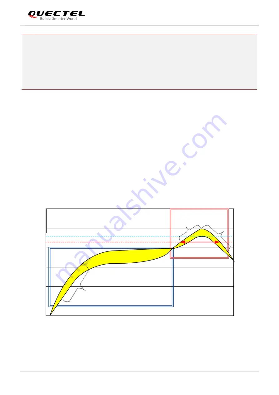
It is suggested that the peak reflow temperature is 238
–
246 º
C, and the absolute maximum reflow temperature is
246 º
C. To avoid damage to the module caused by repeated heating, it is strongly recommended that the module
should be mounted after reflow soldering for the other side of PCB has been completed. The recommended reflow
soldering thermal profile (lead-free reflow soldering) and related parameters are shown below.
Tem p. (
°
C
)
R eflow Z one
S oak Z one
246
200
220
238
C
D
B
A
150
100
M ax slope: 1~3
°
C
/s
C ooling dow n slope:
-1.5 ~ -3
°
C
/s
M ax slope:
2~3
°
C
/s
Figure 44: Recommended Reflow Soldering Thermal Profile
Table 38: Recommended Thermal Profile Parameters