
GV75W User Manual
TRACGV75WUM001
‐ 8 ‐
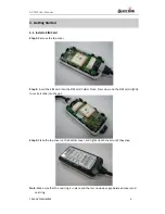
2.3.
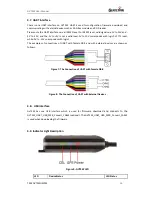
Interface Definition
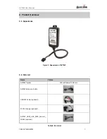
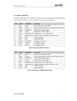
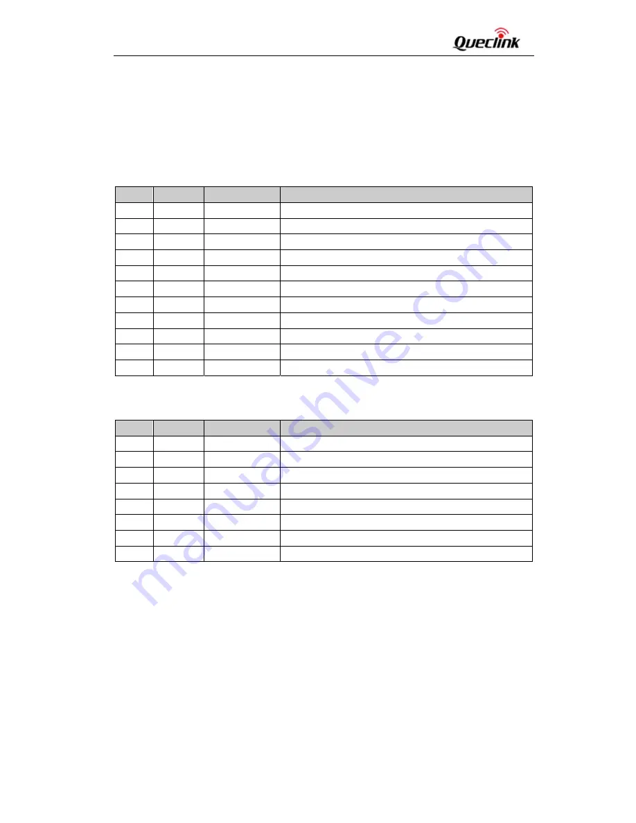
GV75W has 11 interfaces which include the connection for power, ignition input, digital input, digital
output, USB, TXD and RXD, etc. The user cable info is shown in the following table.
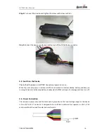
Table 4: Description of GV75W Interface
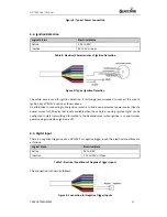
Table 5: Description of GV75W Extension Cable
Index
Colour
Description
Comment
1
Red
Power
External DC power input, 8‐32V
2
Black
Ground
System ground (connected to the vehicle’s frame directly)
3
Yellow
Digital input
Digital input, negative trigger
4
White
Ignition
Ignition input, positive trigger
5
Green
Digital output2
Digital output, low side 150mA max
6
Blue
Digital output1
Digital output, low side 150mA max with latch
7
Purple
TXD
UART TXD, RS232
8
Gray
RXD
UART RXD, RS232
9
Orange
USB_VBUS
USB power connector
10
Brown
USB_DM
USB digital negative
11
Pink
RXD_DP
USB digital positive
Index
Colour
Description
Comment
1
Red
Power
External DC power input, 8‐32V
2
Black
Ground
System ground(connected to the vehicle’s frame directly)
3
Yellow
Digital input
Digital input, negative trigger
4
White
Ignition
Ignition input, positive trigger
5
Green
Digital output2
Digital output, low side 150mA max
6
Blue
Digital output1
Digital output, low side 150mA max with latch
7
Purple
TXD
UART TXD, RS232
8
Gray
RXD
UART RXD, RS232


