GV75W User Manual
TRACGV75WUM001
‐ 13 ‐
3.7.
UART Interface
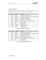
There is one UART interface on GV75W. UART is used for configuration, firmware download, and
communicating with external devices such as CAN Bus module and RFID reader.
Please note the UART interfaces are all RS232 level. For RS232 level, valid signals are 3V to 15V and ‐
3V to ‐15V, and the ‐3V to +3V is not a valid level. 3V to 15V corresponds with logic 0 of TTL level,
while ‐3V to ‐15V corresponds with logic 1.
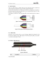
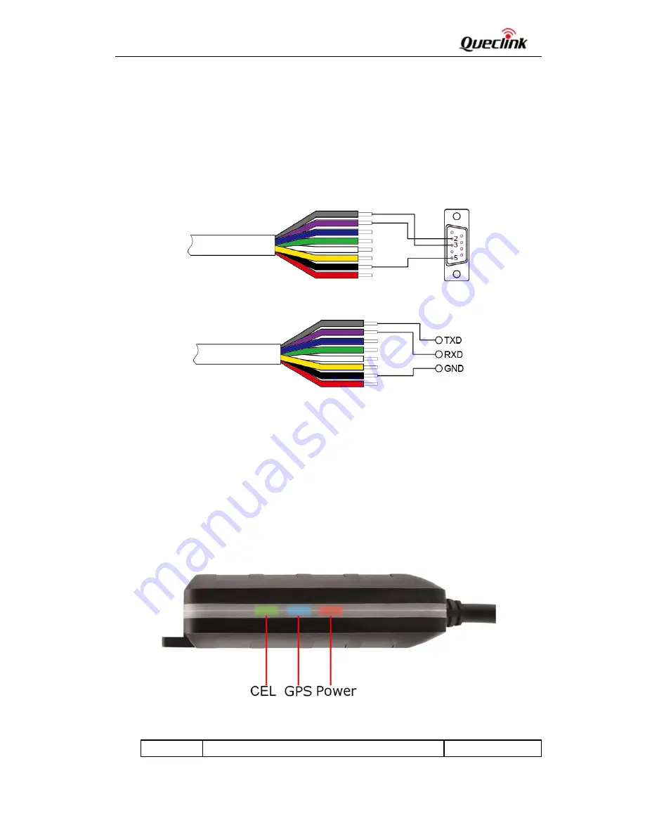
The examples of connections of UART with female DB‐9 and with external devices are shown as
follows.
Figure 7: The Connection of UART with Female DB‐9
Figure 8: The Connection of UART with External Devices
3.8.
USB Interface
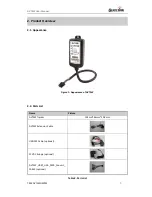
Gv75W has one USB interface which is used for
firmware download and connects to the
GV75W_UART_USB_PWR_Convert_CABLE (optional)
. The
GV75W_UART_USB_PWR_Convert_CABLE
is used when downloading the firmware.
3.9.
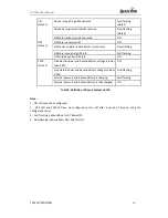
Indicator Light Description
Figure 9: GV75W LED
LED
Device Status
LED Status


