background image

GV75W User Manual


TRACGV75WUM001                             

                                                                                                    ‐ 15 ‐ 

4.


Troubleshooting and Safety Info


4.1.


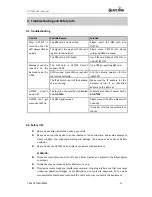
Troubleshooting 

Trouble 

Possible Reason 

Solution 

After  GV75W  is 
turned on, the CEL 
LED always flashes 
quickly. 

The SIM card is not inserted. 

Please  insert  the  SIM  card  into 
GV75W. 

The signal is too weak; GV75W can’t 
register to the network. 

Please  move  GV75W  into  places 
with good GSM coverage. 

The SIM card is PIN locked. 

Use  SIM  card  without  SIM  PIN,  or 
unlock SIM PIN. 

Messages  can’t  be 
reported  to  the 
backend  server  by 
GPRS. 

The  SIM  card  in  GV75W  doesn’t 
support GPRS. 

Try a GPRS supporting SIM card. 

APN is wrong. Some APNs cannot visit 
the Internet directly. 

Ask  the  network  operator  for  the 
right APN. 

The IP address or port of the backend 
server is wrong.   

Make  sure  the  IP  address  for  the 
backend  server  is  an  identified 
address on the Internet. 

GV75W 

doesn’t 

power off. 

The function of power key is disabled 
by 

AT+GTSFR

Enable the function of power key by


AT+GTFKS

GV75W  can’t  get 
successful GPS fix. 

The GPS signal is weak. 

Please move GV75W to a place with 
open sky. 

It is better to let the top surface face 
the sky.   


4.2.


Safety Info 


Please do not disassemble the device by yourself.   


Please do not put the device in an overheated or too humid place, and avoid exposure to 

direct  sunlight.  Too  high  temperature  will  damage  the  device  or  even  cause  battery 
explosion.   


Please do not use GV75W on an airplane or near medical equipment.


WARNING:


This device complies with part 15 of the FCC Rules. Operation is subject to the following two 

conditions: 


This device may not cause harmful interference, and   


This device must accept any interference received, including interference that may cause 

undesired  operation.Changes  or  modifications  not  expressly  approved  by  the  party 
responsible for compliance could void the user’s authority to operate the equipment. 

Summary of Contents for GV75W

Page 1: ...GV75W User Manual TRACGV75WUM001 0 GV75W User Manual WCDMA GSM GPRS GPS Tracker TRACGV75WUM001 Version R1 00...

Page 2: ...ustomer s possession Furthermore system validation of this product designed by Queclink within a larger electronic system remains the responsibility of the customer or the customer s system integrator...

Page 3: ...7 2 1 Appearance 7 2 2 Parts List 7 2 3 Interface Definition 8 3 Getting Started 9 3 1 Install a SIM Card 9 3 2 Switch on the Device 10 3 3 Power Connection 10 3 4 Ignition Detection 11 3 5 Digital I...

Page 4: ...LIST 7 TABLE 4 DESCRIPTION OF GV75W INTERFACE 8 TABLE 5 DESCRIPTION OF GV75W EXTENSION CABLE 8 TABLE 6 ELECTRICAL CHARACTERISTICS OF IGNITION DETECTION 11 TABLE 7 ELECTRICAL CONDITIONS OF NEGATIVE TR...

Page 5: ...TION 11 FIGURE 3 TYPICAL IGNITION DETECTION 11 FIGURE 4 CONNECTION FOR NEGATIVE TRIGGER INPUTS 11 FIGURE 5 CONNECTION TO DRIVE AN LED 12 FIGURE 6 CONNECTION TO DRIVE A RELAY 12 FIGURE 7 THE CONNECTION...

Page 6: ...GV75W User Manual TRACGV75WUM001 5 0 Revision History Revision Date Author Description of Change 1 00 2016 09 09 Super Zhao Initial...

Page 7: ...on and extends battery life through sophisticated power management algorithms System integration is straightforward as complete documentation is provided for the full featured Track protocol The Track...

Page 8: ...Overview 2 1 Appearance Figure 1 Appearance of GV75W 2 2 Parts List Table 3 Parts List Name Picture GV75W Tracker 102mm 46mm 20 5mm GV75W Extension Cable USB 232 Cable optional 12V DC Supply optional...

Page 9: ...on input positive trigger 5 Green Digital output2 Digital output low side 150mA max 6 Blue Digital output1 Digital output low side 150mA max with latch 7 Purple TXD UART TXD RS232 8 Gray RXD UART RXD...

Page 10: ...2 Insert the SIM card into the SIM card holder Note Press down on the SIM card slightly to make it slide into the slot Step 3 Place the top cover on the bottom cover and tighten both covers until they...

Page 11: ...urn on When the external power is removed GV75W will switch to internal backup battery and keep on running When internal backup battery is exhausted GV75W will report a message and then turn off 3 3 P...

Page 12: ...M radio that is only available when the vehicle is running Ignition signal can be configured to start transmitting information to the backend server when ignition is on and to enter power saving mode...

Page 13: ...ditions of Digital Outputs Note The relay output can be latched by the software so even if the GV75W is restarted or powered down in some cases the relay output will not change To use the latch functi...

Page 14: ...orresponds with logic 0 of TTL level while 3V to 15V corresponds with logic 1 The examples of connections of UART with female DB 9 and with external devices are shown as follows Figure 7 The Connectio...

Page 15: ...GPS info ON PWR Note 2 No external power and backup battery voltage is lower than 3 35V OFF No external power and backup battery voltage is below 3 55V Slow flashing External power in and backup batte...

Page 16: ...Internet GV75W doesn t power off The function of power key is disabled by AT GTSFR Enable the function of power key by AT GTFKS GV75W can t get successful GPS fix The GPS signal is weak Please move GV...

Page 17: ...ill not occur in a particular installation If this equipment does cause harmful interference to radio or television reception which can be determined by turning the equipment off and on the user is en...

Reviews: